Just got around to getting the bed and waste board done. I built a tramming apparatus out of a short piece of aluminum T Track. Anyways, my tramming from side to side is off slightly. I looked over the instructions and sienci provides two eccentrics for this problem if you have it. Either way, the instructions have you just replace the upper left shoulder bolt with an eccentric and 6 by 25 button head bolt. That is fine but the eccentric wont move the spindle mount unless I remove the right hand shoulder bolt too. Im thinking I might need to use both eccentrics and just not use the shoulder bolts. Anyone run into this and if so what did you do?
Just ran across this post. Complete instructions for squaring and tramming the Altmill can be found in Altmill resource section on website. Scroll down in the left column to the Handbook section. That section was posted there in November 2025. Hope that helps!
I tried to tram the altmill 4x4 today and I was not able to adjust the gantry enough to get it corrected even after adding the bussing in the top right corner on the right side of the gantry.
I’ve been in CNC hell trying to tram the nod on my AltMill 4x4. So far everything on the sienci website has been worthless for me. What i have found has been incomplete, has errors, confusing, or wrong. Possibly it’s just me, but i don’t think so…
How far is it out? I have not redone mine yet but I think nod is done by alignment of the gantry end…I have not looked back at the directions yet but will in a few days
Mine was off by about 1/4" .
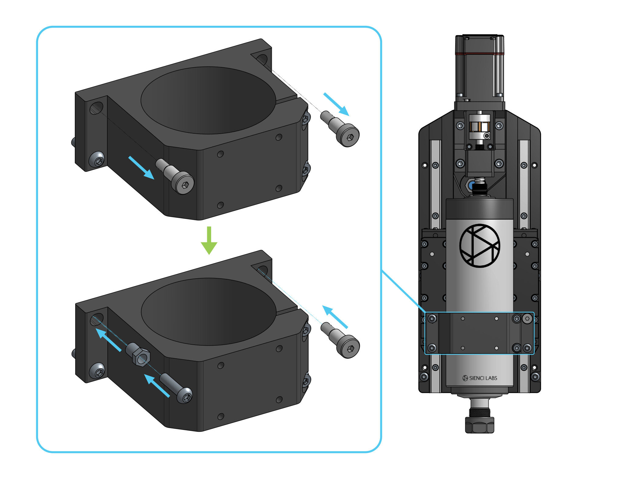
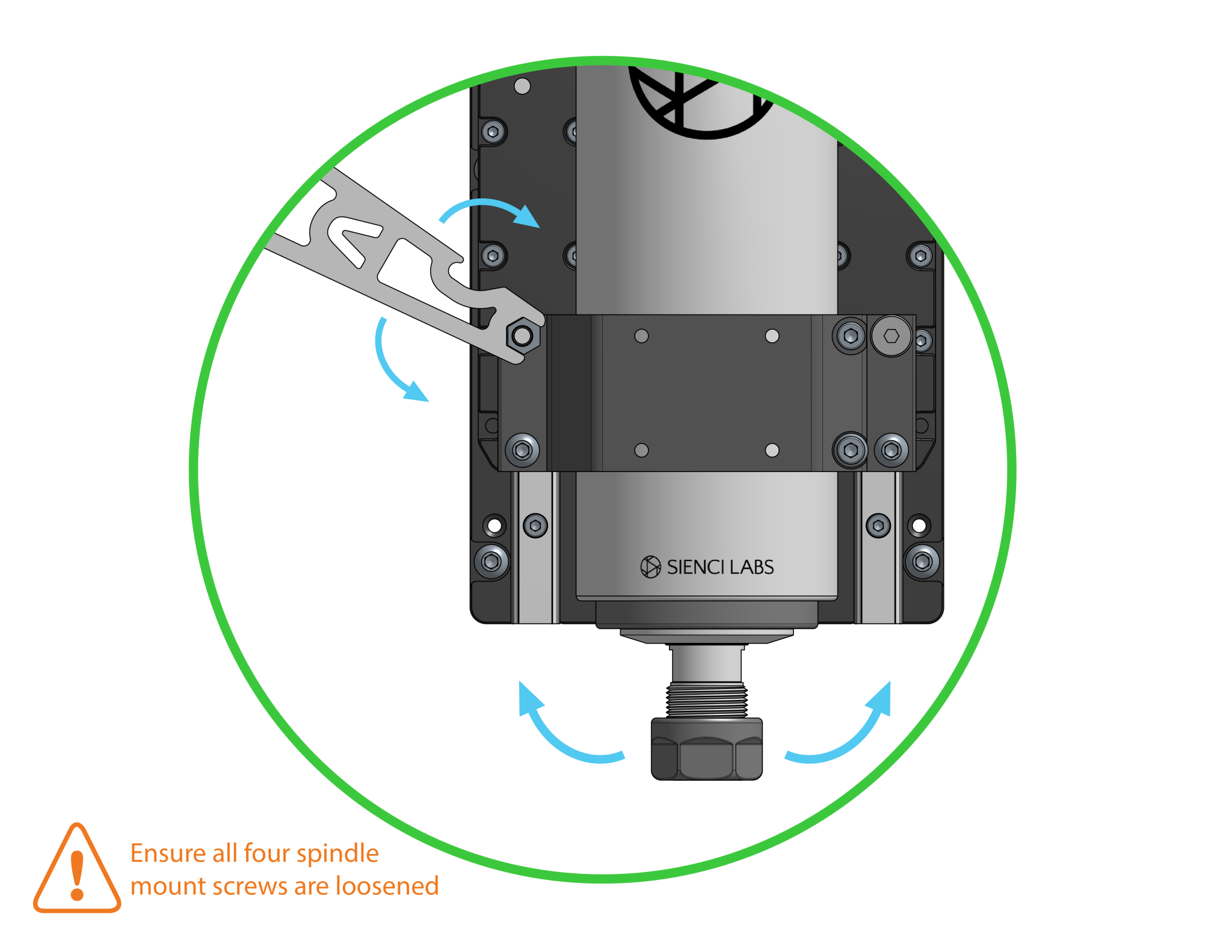
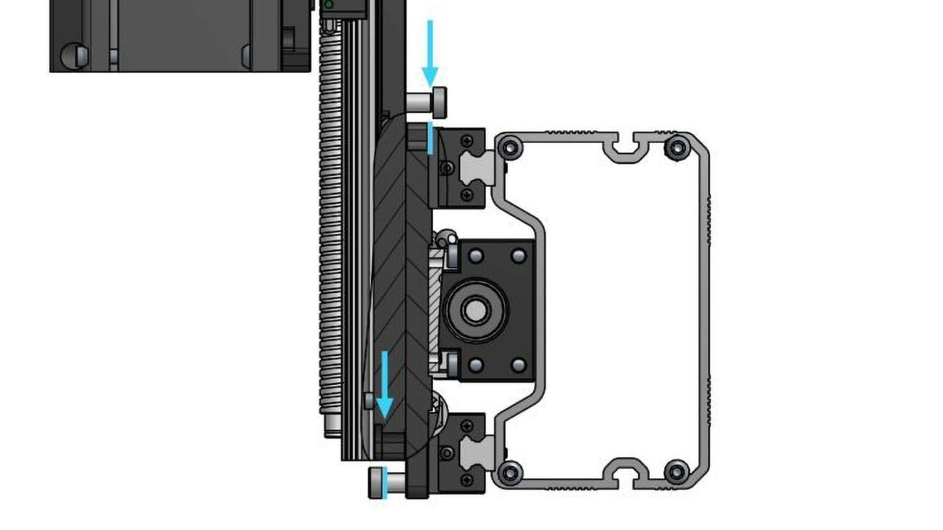
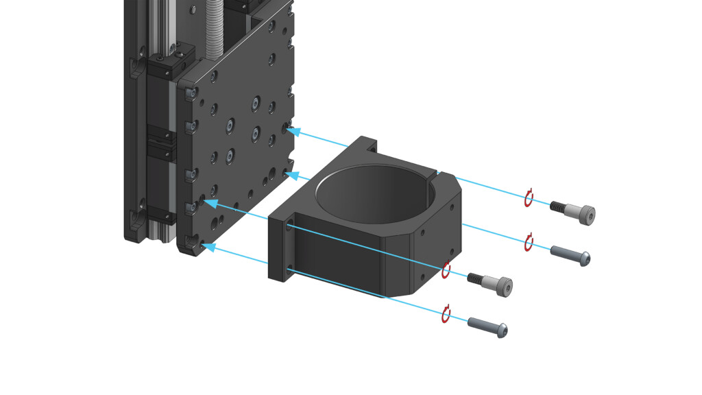
The two most important pics are shown below. You need to complete remove the top left bolt and just loosen the other three to allow some play. After inserting the eccentric bushing with M6-25mm in the top left bolt position you tighten it that M6 bolt you just barely finger tighten it. Then you have to use that wrench like tool to turn the eccentric bushing which will cause the spindle to tilt slightly to the left or right. When I verified it was correct you have to hold that eccentric bushing in place with the wrench and tighten the M6-25mm bolt at same time. Then tighten the other three bolts you loosened earlier.
For nod you have to loosen the bolts holding the entire Z axis plate onto the gantry and add a shim between the two top bolts. You have to provide the shims yourself and not use the eccentric bushing.
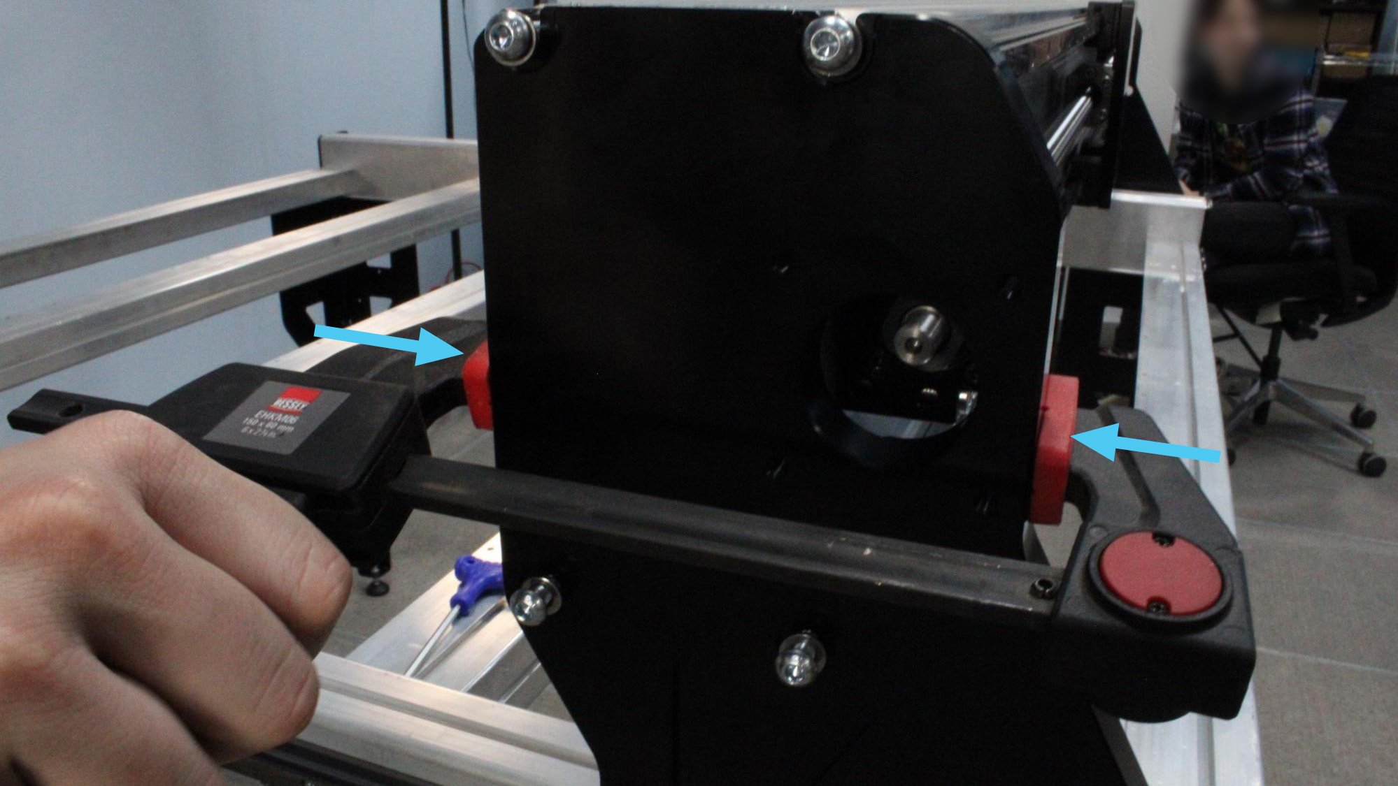
I will note mine was perfectly aligned in the nod direction. When you install the gantry you have to make sure you have the bolts used to fasten it loose on both sides and then use a clamp to make sure the left side is fully seated. It’s possible it isn’t since the clamp can be positioned wrong and not allow it to push it all the way on.
The clamp on left side has to be touching the silver horizontal gantry section only and not the black side plate otherwise it won’t seat properly and nod will be off on the spindle.
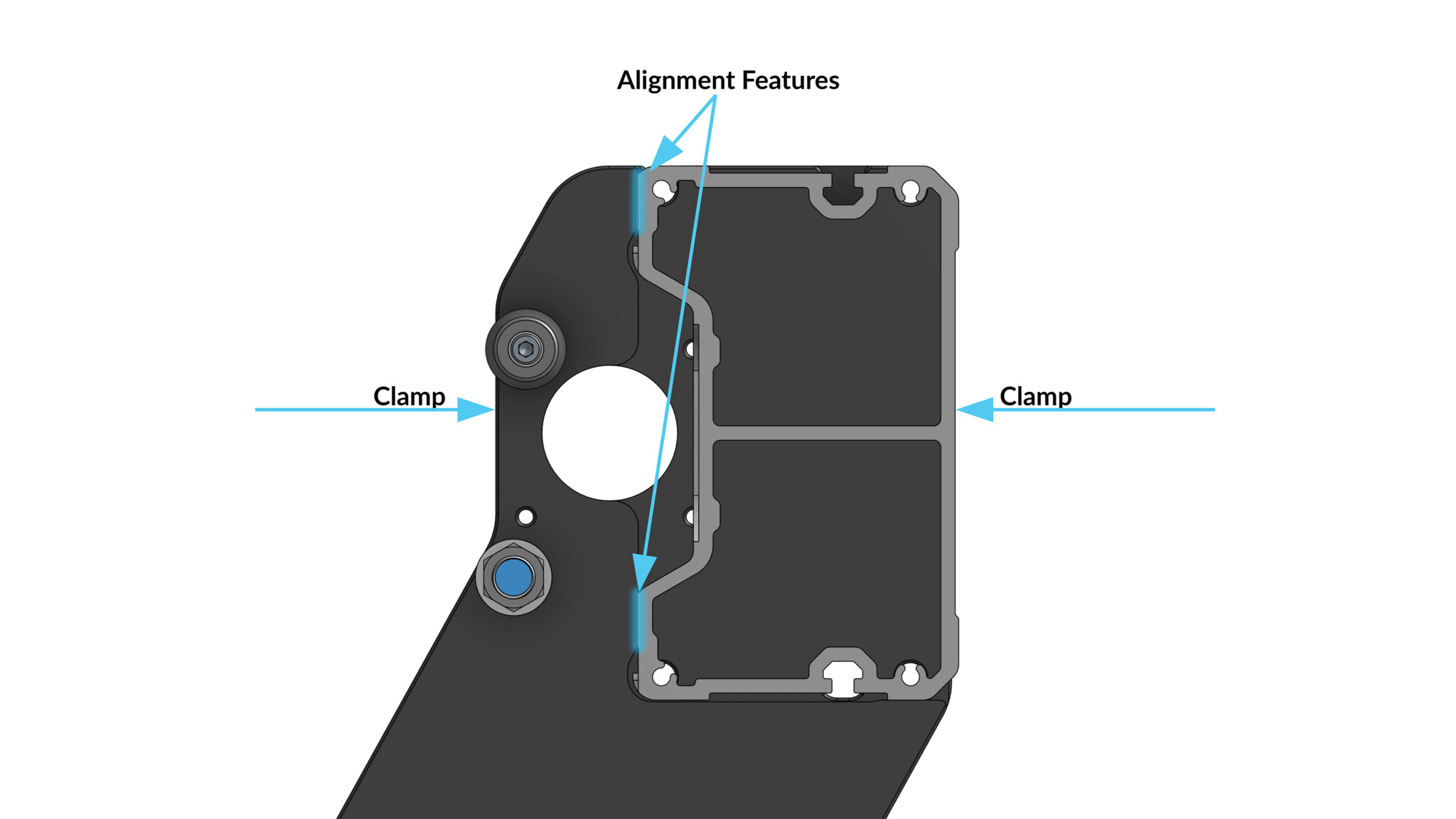
They also have a picture trying to show you how to verify the gantry is fully seated. The blue vertical lines are where it makes contact with vertical lips on the black side plates.
I’m lost in left field. Why do you think your method of adjusting the nod is correct? I think it is wrong, however, I’m totally confused!
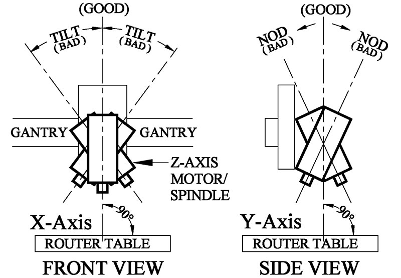
At the Sienci website, Tramming LongMill or Altmill – Sienci Labs they discuss discuss adjusting the tilt and nod, but I cannot get my head wrapped around the NOD adjustment. They include the following image.
They instruct us to loosen the 2 shoulder bolts. I’ve searched all of documents I’ve downloaded for the Altmill and searched the website. I cannot find anything that identifies the “shoulder bolt”. Where are the two bolts??? In the above image, the two bolts “should be” obvious and easy to adjust.
Did you go to the Z-axis assy inside the Altmill assembly instructions? It shows where they go. You might have to raise the Spindle to see the ones in the back. Are you planning to shim between the plates? I just used the wood clamp upon assy and my nod was good.
@beerbarrel I’m surprised that so many users seem to need to tram their Altmill. If the x rail is attached to the gantry plates properly, nod is supposed to be fairly good.
@Jgt1942
So it would be worthwhile checking how the x rail is attached to the plates before tramming. There’s a registration edge on the plate and the rails need to be tight against it (see post with the clamps from @DavidB above)
I hear you Chucky and mine was good. I looked at the NOD instructions and it seems pretty straightforward other than what looks like an incorrect image.