I put my LongMill together almost two weeks ago and for the most part it seems to be working fine for a couple of simple signs and such. As I’ve really started to look at the cuts though I’m starting to realize it does not quite cut round, or arcs.
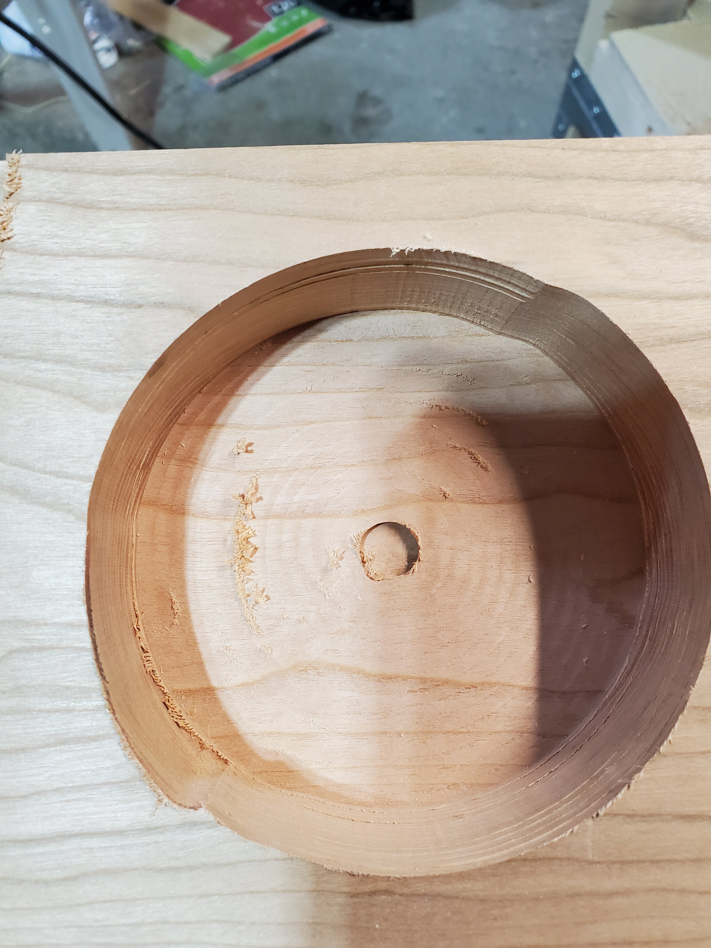
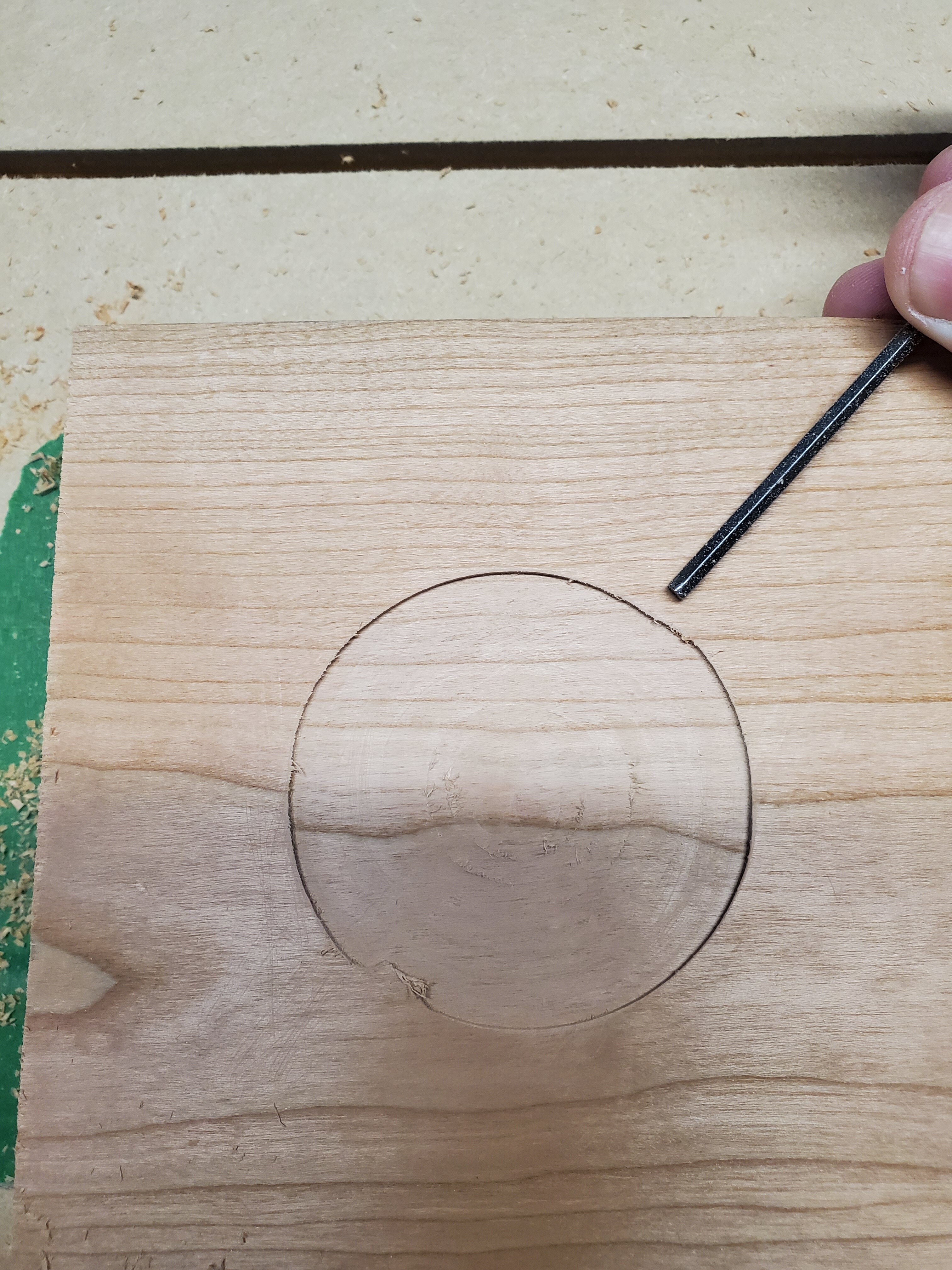
The one photo below shows the start of a pocket cut gor a 5 inch round box using a 1/4 inch downcut bit (2 flute) as sold by Sience. I had been cutting this piece of hardwood using a feed rate of 60.0 inches and a plunge rate of 12 inches. The other photo shows a cut that was further along with the same settings. Both have the issue at the same point of the circle. The notch/ bump on the lower left for both pics is where the bit track out gor the next curcular cut.
I’m new to the Long Mill and I’ve checked the tightness of everything I can think of. Maybe something is too tight? I’ve also noticed that when moving the gantry forward along the Y it seems to have a bit of a studder step where both ends of the X axis seem to move separately…just a fraction at a time.
Any suggestions where I should start troubleshooting?
Wow, that looks terrible. It looks like the problem occurs just before the maximum and minimum X or Y travel, depending on how the piece was mounted on the machine. That should be a clue. I would try the cut in free air or maybe foam to see if the same thing happens with no load on the bit. I see ridges that suggest there is slop in the movement but other than that I don’t have much to suggest.
This is just a guess but have you checked the coupler set screws?
They were mounted more or less as shown in the pics. Using the clock, the distortion was between 1 and 2 with the corresponding distortion between 7 and 8. Ill give those things a look though.
In that case, the problem occurs when the Y axis is decelerating and the X axis is accelerating regardless of the direction of travel. Just for laughs try cutting a square. Cutting a square will cause the axis to move independently of one another,
I will tomorrow. I had also done this today, a camp trailer sign, before I tried the other project, and just putting some finish on it tonight I saw where it was doing the same thing, slightly, on the curve on the upper right. Just slightly.
It’s a little hard to tell in these photos but I think I see some distortion in the square corners too. In paticular the upper left corner in the first photo (lower left when the orientation is correct)
Now I really suspect some backlash in the movement of the machine that cause a problem when changing direction. And it would seem to require some force before it rears it’s ugly head.
From the pic, it looks like the problem is at the start of each pass. If I’m mistaken, pass on the rest of this.
Can you ramp in with whatever CAM software you are using. If so, set ramps to 1.5" and try it again. I used to get those “dwell marks” when cutting the lids for small boxes out of hard maple. Using ramps and a last pass of a few thousandths completely eliminated them.
I went through quite a bit of frustration and tinkering to get my machine sorted out. It’s hard to know just how much tightness is right on each of the wheels, backlash nuts etc. In the end I learned I had everything too loose, as I had a few bolts come out and my Y axis get our of square. An evening patiently adjusting and resetting things, and learning about how not to crash the machine in to the ends of the axis (which can throw things out of sync if you have anything loose already) was well worth it.
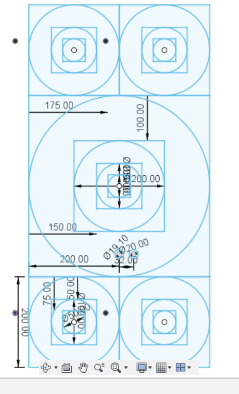
In the end I grabbed a piece of scrap MDF that was pretty large and I cut a pattern in it with circles inside squares. Screen capture attached. Each of the squares was the exact size it should have been and the circles were perfectly round. Took me quite a while to get to that point, but most of that was lack of knowledge and understanding (and lack of locktite - which I still need). Also, learning to avoid crashing the axis helped a lot.
I apologize, I added various things to it and it’s got a few confusion distractions. It’s a 400 mm x 800mm (happened to be roughly the offcut I had and it covered most of the bed on the Y axis) and the squares are 400mm, 200mm, 100mm and 50mm with matching circles inside them. Make sure you tell it to do a “tool inside boundry” when cutting, and then you can use the end of your tape pushed up against the cut line for one end of your measurement to check it, and read off the far end. My squares were bang on and I could see the circles were properly round. Definitely could not have done this within the first two weeks though…
I learned that GRBL, the software running on the Longboard, sets your “real machine home” 0,0,0 to whatever the position of the router is at power on. If you have limit switches you can “re-home” the machine, but the Longmill doesn’t come with these by default (@chrismakesstuff you really should consider offering some 3D printed mounts and simple end-stops as an add-on).
If you don’t set your default “real” home position to a known position, the liklihood of crashing you axis due to sending the machine somewhere at the end of a carve (at least if you’re using Fusion 360) is high. Reading up, I understand the it’s fairly standard in the business to send your machine to top Z height and the distant rear corner at the end of a job. Not a hard and fast rule, but you’ll notice it in photos and videos now that I’ve mentioned it. I started making sure my machine was in that position at shut down and I added a macro to go “Z-Up and return to real home” and I do that every time before shut down and also when I need the router out of the way. Ever since, I’ve had a lot fewer problems.
I’ve been cutting precision 19mm, 20mm and 25mm dog holes for machine metal dogs and they are coming out dead accurate (using the circular 2D operation). I talked a bit more about my settings in another post.
@jwoody18 Jeff: Good stuff. To add to it, I learned from discussions on the Google UGS list that UGS resets both the machine coordinates and the work coordinates when you zero XYZ. That threw me off until I learned it. I had read about using G28.1 to set a machine zero position that you could then use to reference off. You could move your machine to the front left corner, for example, enter G28.1 and you would have a position that was saved by grbl in the eeprom of the controller. Then, any time you wanted, you could enter G28 into UGS and the machine would return to that coordinate. This was like having homing switches. However, that does not work with UGS. With UGS you can enter G28.1, jog the machine anywhere, enter G28 and it will return to the “home” spot. Great! However, if, after entering G28.1, you close UGS, you turn the machine off or you set an XYZ0 for your job, UGS overrides the G28.1-set spot. Then, crazy things can happen.
I am slow, so it took a lot of back and forth with some UGS/grbl guys to get this through to me.
All this said, you’re right, having homing switches is the way to go. I have the switches, the wire and the capacitors. I’m working on the mountings.
@jwoody18 Jeff: Re: your squares and circles. What did you find when inputting bit sizes in your software? Bill Korn found that the Sienci aluminum bits that he bought were not really .125 as advertised. They were .118. I found something similar with some single flute bits that I bought for plastic. If I entered .125 in the software, the dimensions of the holes that I cut were off. I had to play for a while until I settled on .1175.
Did you need to play with those dimensions before you saw accurate results?
Grant, are you sure about this? I have started trying to return my router to the rear right corner every time I stop (even if I manually crash in to the axes for a few mm just to be sure I am in the right spot - bring on the homing switches!) and then when power off it saves. When I start my day I usually zero near the front left corner. I have a macro to return the machine to what is “Z fully up, XY machine zero” (sorry, don’t have the G-code handy, I copied it out of the end of my latest fusion file) and I can flip between them.
When a job is done it goes to the rear right corner, but I can summon the machine to the XYZ WCS zero I set or reset anywhere on the board without losing what I refer to as absolute Zero in the right rear corner. Do you know when UGS made the change? I’m on August 2019, but I think you said you’re on a newer version now? I wonder if they updated it?
Or perhaps, as there are multiple layers of coorindate systems, we’re both right. Later on when I’m at the machine I’ll post the macro I use and we can see what’s what.
I have to admit that I didn’t put the caliper on my bits once I added them to my tool library. I don’t recall noticing that my bits were undersized, but I was mostly using a Yonico compression bit from Amazon (very happy with it). I am pretty sure that’s what I used to do my circles and suqares although I may have used the Sienci downcut. Er… I can’t recall and I also um… well I’ve been lying to Fusion and just picking my compression bit even if I intend to use the downcut bit so perhaps I better double check my bit diameters.
I had a bit slip last night and the machine crashed hard on the X axis as it tried to push across the X with the Bit loose and jammed in a deep cut on baltic birch. I need to carefully check my measurements today somehow before I started the second part of my tiled cut.
@Duke How are you making out with your circles and squares now?
Likely due to my own inexperience, I had to go through almost every major nut and bolt on my machine and patiently adjust and retighten them. I suspect I was over-concerned about making them too tight during the initial build. Chris says in his video series “these need to be tight, these be careful not to over tighten” but it’s hard to quantify what he means without a torque reference I guess?
I realized a few weeks later, after various so-so results from initial projects, that I had a serious issue. I discovered not only was my XZ loose (grabbing the lower right corner I could wiggle it up and down as well as left and right). I then also found that 3 (!) of my bolts had slowly come loose out of the BACK of the router mount. So I had to take the XZ off, tighten those down (sadly I sheared one off the fourth one during the initial build, as the first one I did I used the wrong screw length without realizing it and when tightening it I snapped it. Whomp whomp.).
Also, it took quite a bit of fiddling with the concentric nuts and wheels to get firm tension but not rubbing and to get all four wheels engaged on the Y axes. I was too impatient with this at the outset. If you’re still having issues, go through each pair of wheels methodically and then do a second pass (as adjusting the later ones can impact the early ones the first time around) and make sure you’re happy.
Ever since those changes my results have been really solid.
Hopefully you’re seeing the same good results now?
-Jeff
PS - @chrismakesstuff This brings me back to a suggestion I made months ago that there be a standardized test pattern that is recommended to be run after a machine is set up to confirm accuracy and that can be benchmarked against in future if accuracy slips. Ideally the pattern would cover the whole table area or at least the formally advertised 30x30 surface. That’s probably a better idea as squares and circles work well. so maybe 750x750 mm total area, and put four smaller square and circle combos in the corners and one larger one in the center. And have one set at various 1mm step downs to measure Z depth? Design it to be cut in 3/4" MDF off cut from the table top piece you recommend?
@jwoody18 Jeff: I am using an April 2020 version, but this was the same with the 2019 version that I was using. As to being sure, hell, I’m not “sure” of anything. I can confirm that my results were confirmed with another guy on the UGS group.
Here is what I was trying to do. I had read that you could move your grbl machine to any point in its travel, then enter the code G28.1. That would set a “home” location in the eeprom. It would never change unless you entered G28.1 again. So, I went to the left front corner and entered G28.1. Then I jogged to anywhere. I entered G28 and it returned to the “home” location. This is what I wanted as I now had a location that I could reference from for my jobs.
To test it further, I did the G28.1 trick, then disconnected in UGS from the Mill, and closed UGS. I opened it and connected to the mill. I entered G28 and it was lost. It wanted to go somewhere toward the back right corner. Bummer.
Next test. I did the G28.1 trick, then jogged to the centre of my job. There, I set XYZ0 in UGS. I jogged away from there, and entered G28. Now, if all was well, it should have moved to the left front corner. Instead, it moved back to the XYZ0 position that I had set.
I posted all this to the UGS group, got all kinds of instructions to try, and finally got agreement that, when setting XYZ0 in UGS, it enters a virtual G28.1 code. Also, when shutting down and re-starting UGS, it enters a G28.1 code, so where ever the machine is when it re-starts, that becomes “home” for the purpose of any subsequent G28, at least until XYZ0 is set.
It was as this point that I gave up any further testing. As we agree, hard switches are the answer.
@jwoody18 I have not had bolts fall out, but I have adjusted the delrin wheels a few times. Early on, I realized that the problem was not so much the spacing in the wheels, but that my Y rails were not perfectly parallel. So, the wheels were not too tight vertically. They were binding on the sides of the rails. I had to take all the screws out of the feet and run the mill front to back a couple of times to get the rails parallel to each other. That solved a lot of issues.
Also, I found that lifting up on the X gantry when adjusting the wheels helped me get more consistent results. The weight of the gantry itself puts considerable down force on the wheels, making them seem tighter than they are.
I second both of your steps. @chrismakesstuff these probably already are, but if not, these should be at the top of an FAQ about how to dial in the machine. Maybe on a bright orange piece of printed paper included in the box.