Could there be downward deflection (since you are using a downcut bit) pushing the stock down? 0.5 mm deflection is pretty difficult to spot unless you are looking for it. The other possibility is that the downcut bit is pushing your gantry up just a tiny bit . Again, difficult to spot.
If you have an upcut bit, use that and see what you get. Alternatively, instead of taping the part to the spoil board, screw it down. It would also be interesting to measure the thickness of the tape, especially if you have two layers with crazy glue in between. Tape can be squished. I am also assuming you have 100% coverage of tape for both the spoil board and the part rather than having tape around the circumference and having a small void in the middle.
I don’t actually know how much force is asserted against the board by the bit but these are the only things that jump out at me …
One more thing - my spoil board is slightly warped. Although it was surfaced, I would not at all be surprised if it allowed slight movement.
You could run a second pass (spring pass) to see if that improves things
Oh, one more issue - depending on how you made the gcode file, some programs (fusion) like to default to ‘leave stock’ mode for a finish pass.
To add to @Jens comments about deflection,
The spoil board looks tighter against the table in the corner than further down the X-axis direction, I see only one fastener location in the same tight corner, so it’s possible the spoil board needs to be fastened more securely.
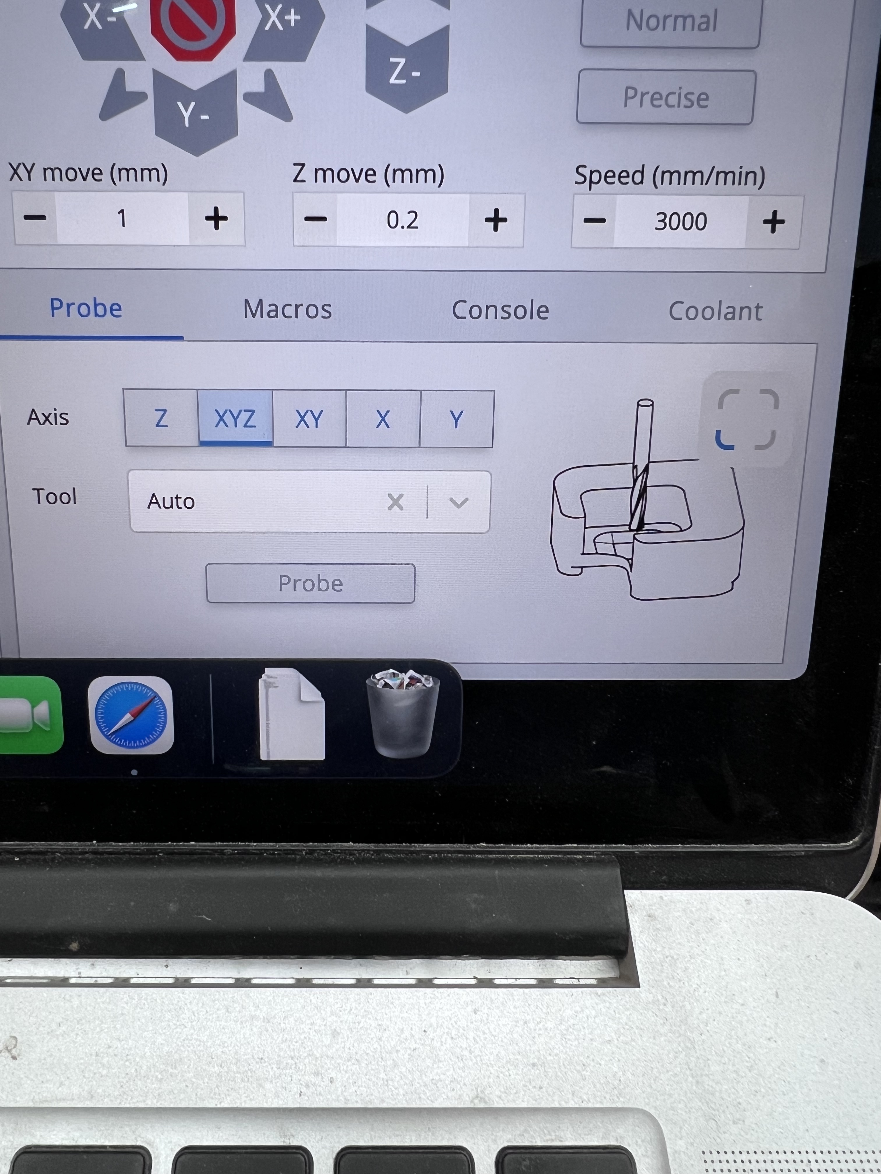
Also something to watch out for, is when probing off the uneven surface of some workpieces, the plate will slightly tilt and set an incorrect Z zero position,
It depends on so many things. You can take apart your whole machine, replace all the v-wheels, tighten up your z-belt, recalibrate your steppers.
Replace resurface wasteboard, rethink clamping and whatnot. You might be able to reduce the offset, or not. It’s a choise to make, hanging on how important it is that your machine cuts exact or that it does not matter that its a wee off.
You can, if the offset is consistant, increase the depth of cut with half a mm on the cad side, and call it a win.
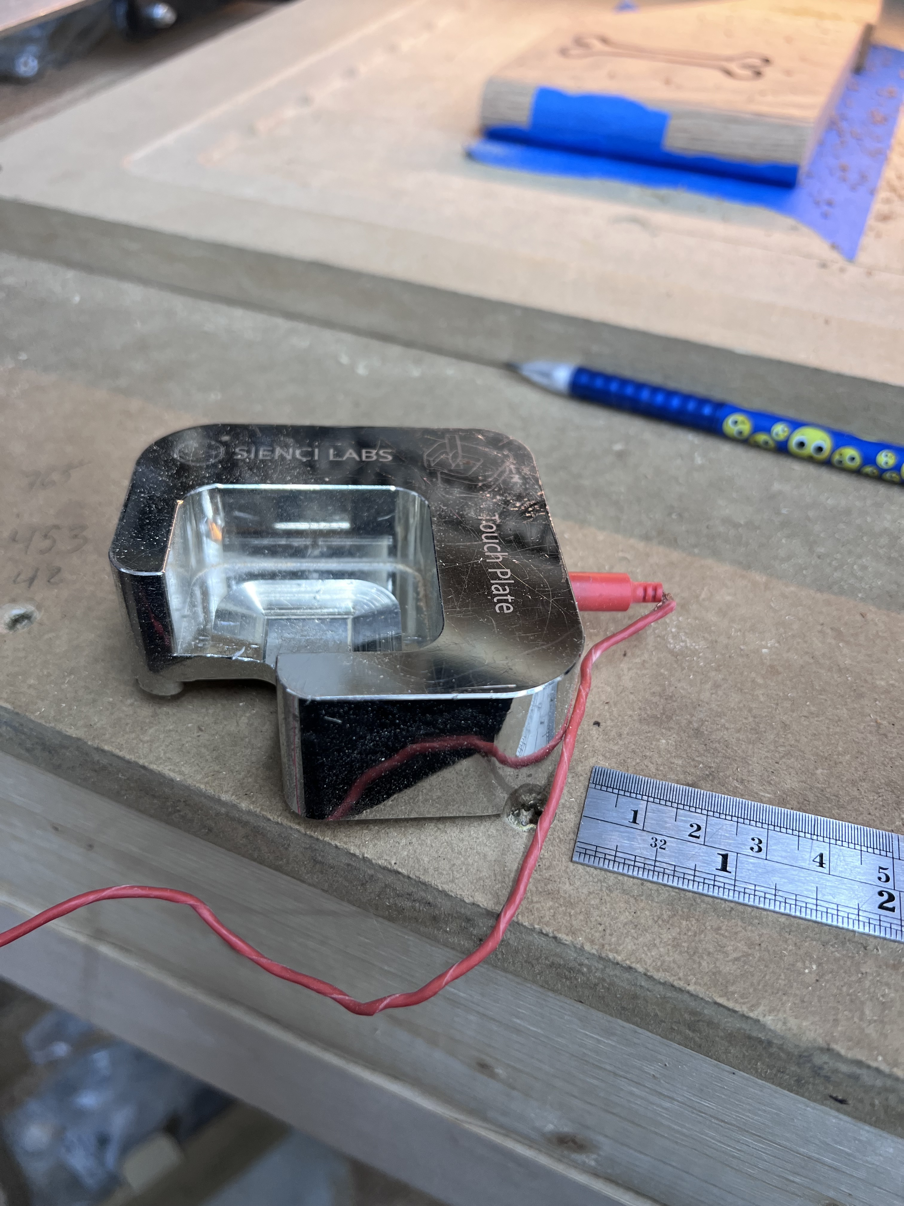
I would however worrie about that touch plate cable. It looks like it got wind into the spindle a few times. They can only do that so many times. (I have tested this.)
I really appreciate the ideas. I will think about how I can test these different ideas. My hope is to just tighten up the tolerance. I don’t “need” perfection but 0.5 mm just seems like too much.
Thanks for the feedback!
lol, yeah the touch plate wires need some love. I bought it this way, so maybe it’s time to fix it. Appreciate the link. Will review that and see what I can do to improve.
Thanks!
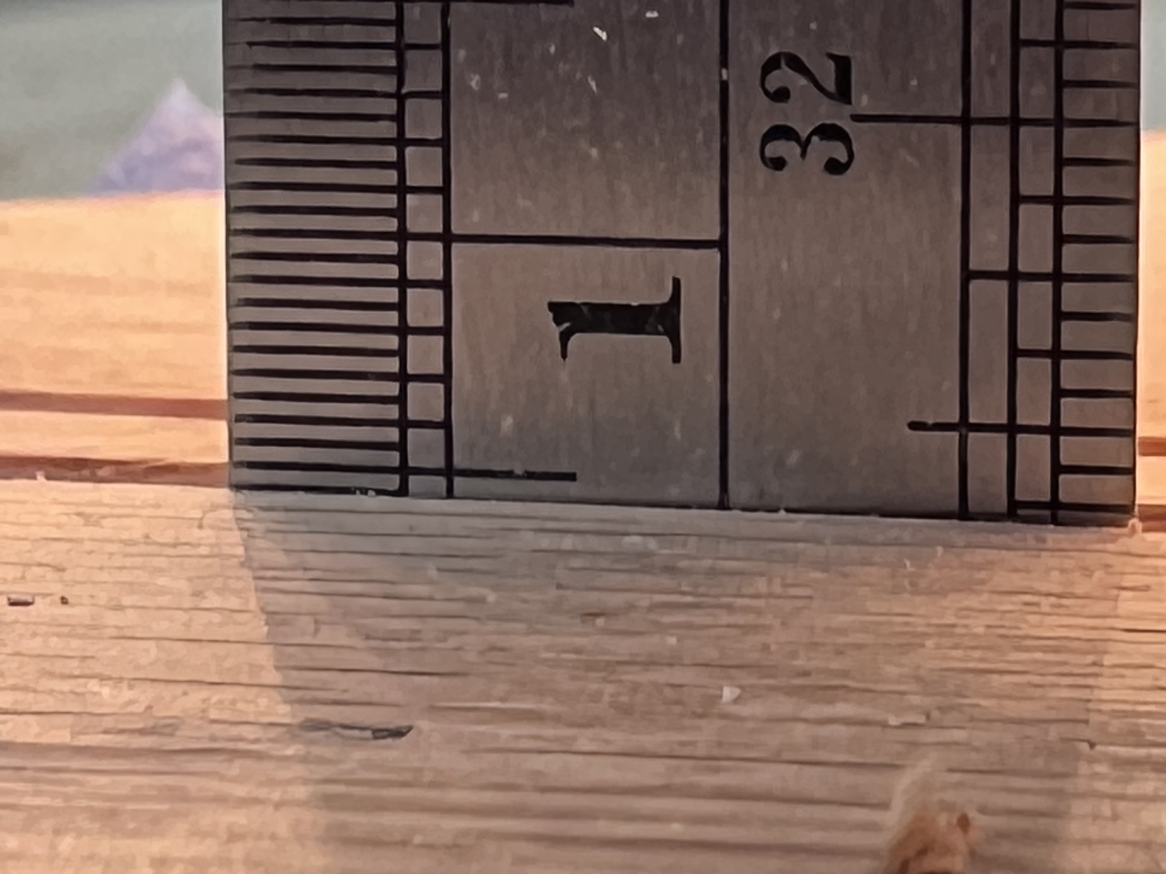
I did redo the cut with an up cut bit. I used the same wood, same mount (never moved from first cut. The depth came out perfectly 5mm! Since I used the same board from the first test I think I can eliminate any squishing issues with the blue tape mounting method.
Not sure what to conclude about the depth of cut being different between bits.
There is one other difference, I manually zeroed the up cut bit and used the touch plate to zero the down cut bit. If the touch plate is causing the error I should be able to reproduce it and also test manual zeroing with the down cut bit.
Ummmm, maybe I am not understanding you but I would say that you have just proven that something is moving because of the cutting forces. You haven’t eliminated squishing.
You have confirmed that the issue is produced due to cutting forces … although at this stage it isn’t known if it is squishing the tape, flexing the spoil board or pushing up the gantry. You have eliminated the possibility of your cutting path leaving stock for a finish pass.
I can’t think of an easy way to test exactly what is moving short of building some sort of overhead arm supporting a dial indicator which then allows you to test for flexing - first the table itself to eliminate a source of error and then the work piece. You should probably use something with a similar diameter as the cutter to apply the force with.
Just thought of another possibility … Could there be play in the vertical position in the router shaft? At rest, the shaft would sit at the lower end of it’s play and even a very slight application of upward force (a downcut bit would push up on the router shaft) would move the router shaft towards the upper end of it’s play.
@mtrain Given this last piece of information, I would check the v wheels on the XZ gantry. Bring the router close to its travel in the front and jog to the middle of the X travel. Turn everything off. Take a hold of the router mount and try to move the router up and down and rock it forward and backwards. There should be no movement.
A simple way to better see movement is to use a phone camera, for example, you can check the X-gantry by placing the camera on top of the Z-axis stepper motor, record facing down and see if there’s movement when pressure is applied to the bottom of the router. Zoom in on the playback to see the motion better.
A more advanced way to check the machine without specialized tools, is to amplify the movement with a straight edge/object.
Here’s my setup to check the Router mount/Z-gantry, X-gantry, X-rail, and Y-gantry all at the same time.
With this method you’re able to pin point the deflection or a loose gantry by visually seeing and comparing the movement.
In my case, I could see the little play I leave in the X-gantry and that the Y-gantries are solid, the deflection in my machine is mainly in the router mount/Z-gantry followed by the X-rail.
I lightly clamp straight edges/rods to the router mount and on the top of the X-gantry, then placing another one between them on top of the X-rail, secured under the drag chain or with tape, and finally one resting on the Y-gantry, between the coupler/clamping nut and a motor spacer/ X-rail bolt. then placing a measuring tool in line with the straight edges and comparing the movement.