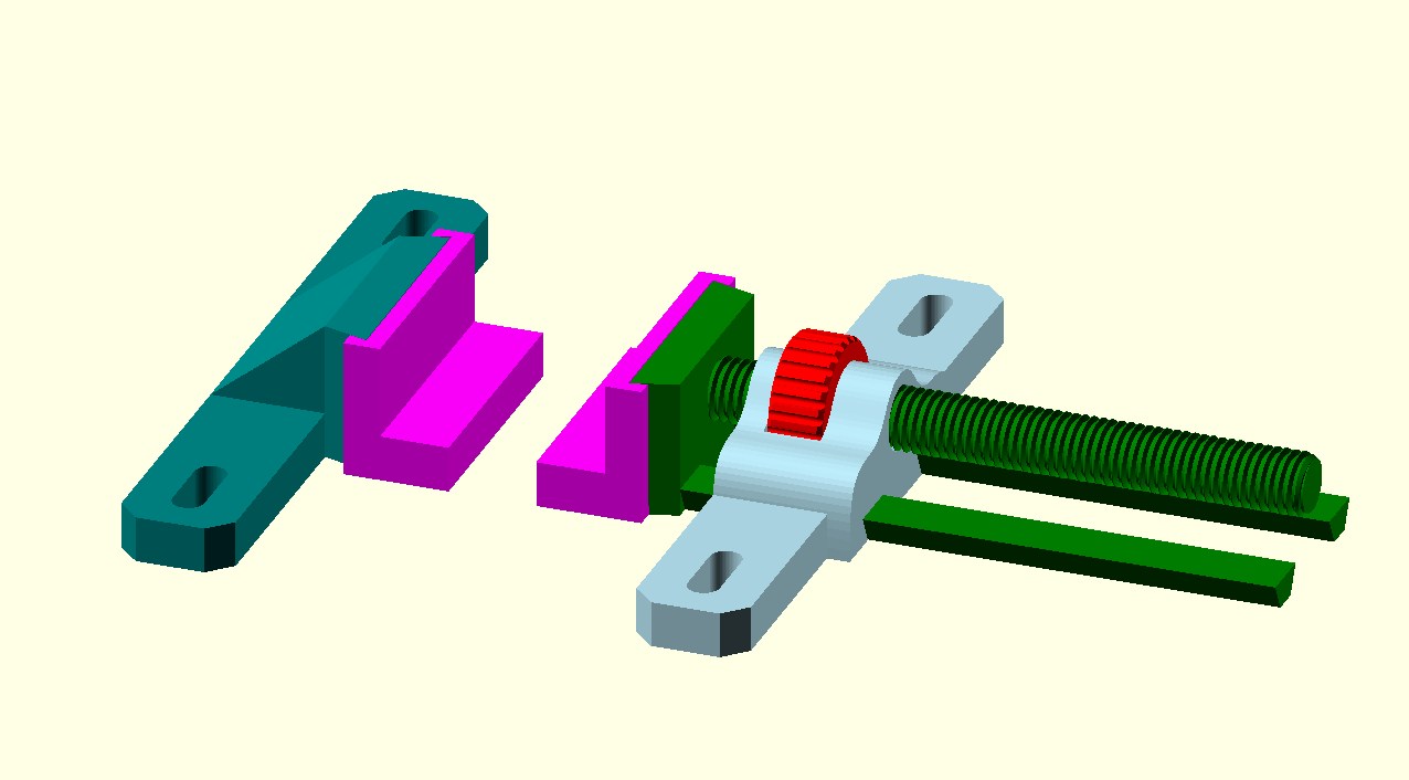
I was thinking about different toe clamp designs awhile back as I wanted a better way to clamp pieces for surfacing and I had a light bulb moment. This is what I came up with borrowing some ideas from my bench vice.
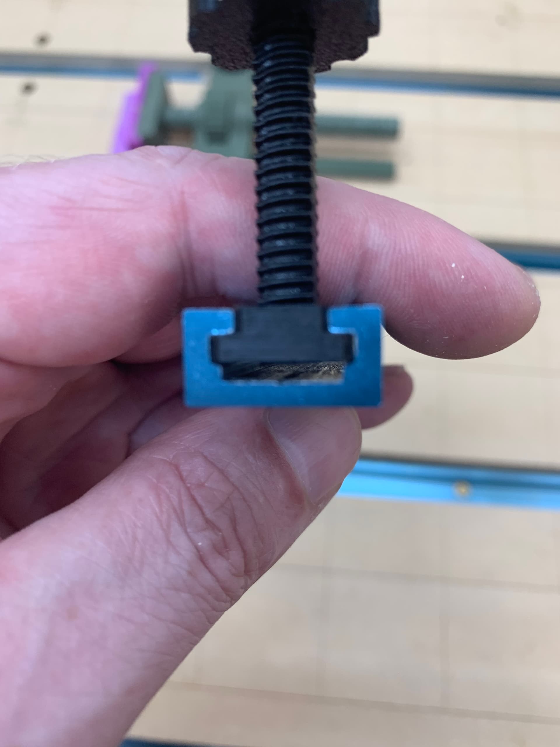
The magenta ‘jaw pads’ as I call 'em are removable and made from a flexible filament with a shore hardness of 98A which is on the stiffer side of flexible. The toe part is 10mm thick on these so I need to make some thinner ones if I want to surface thinner materials.
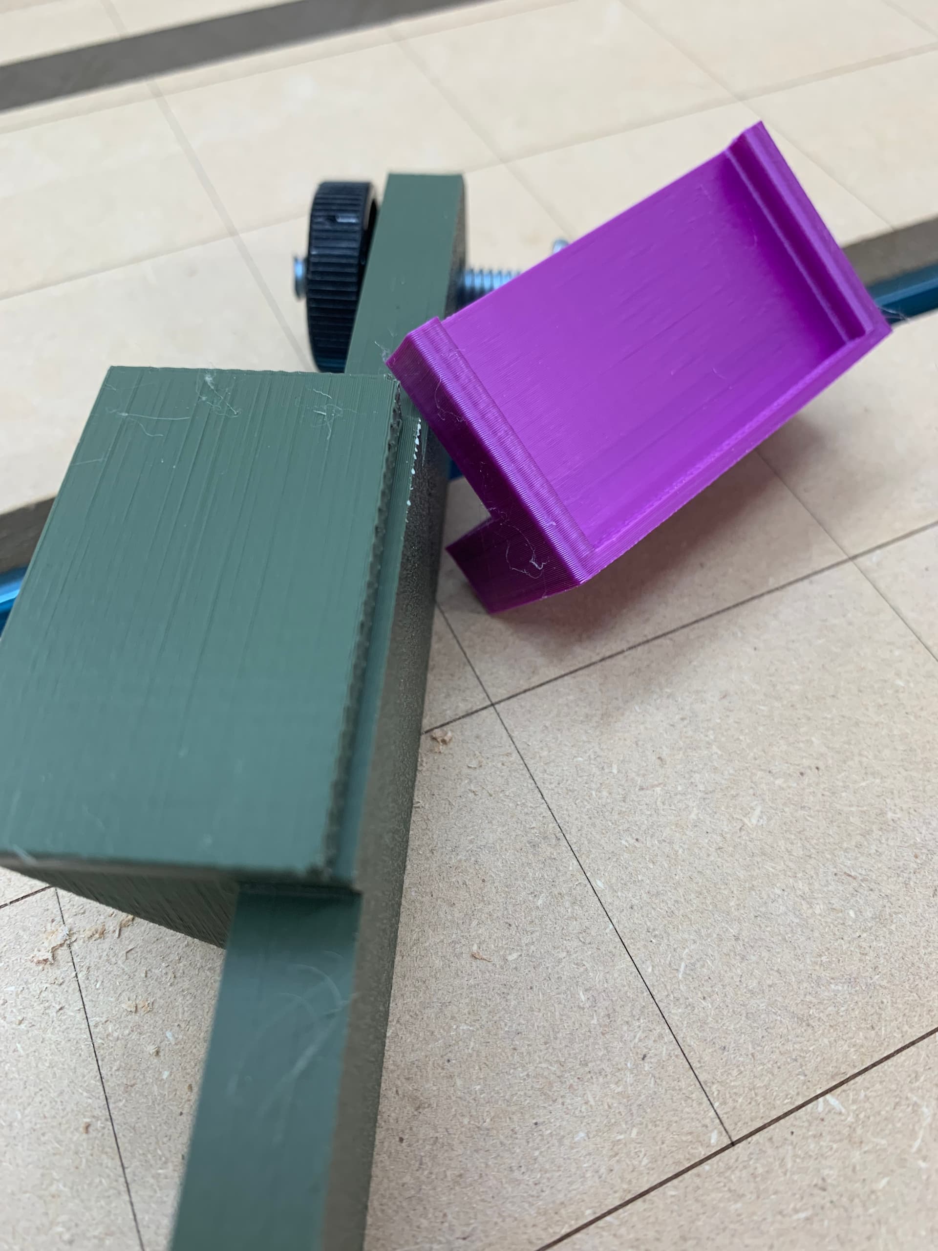
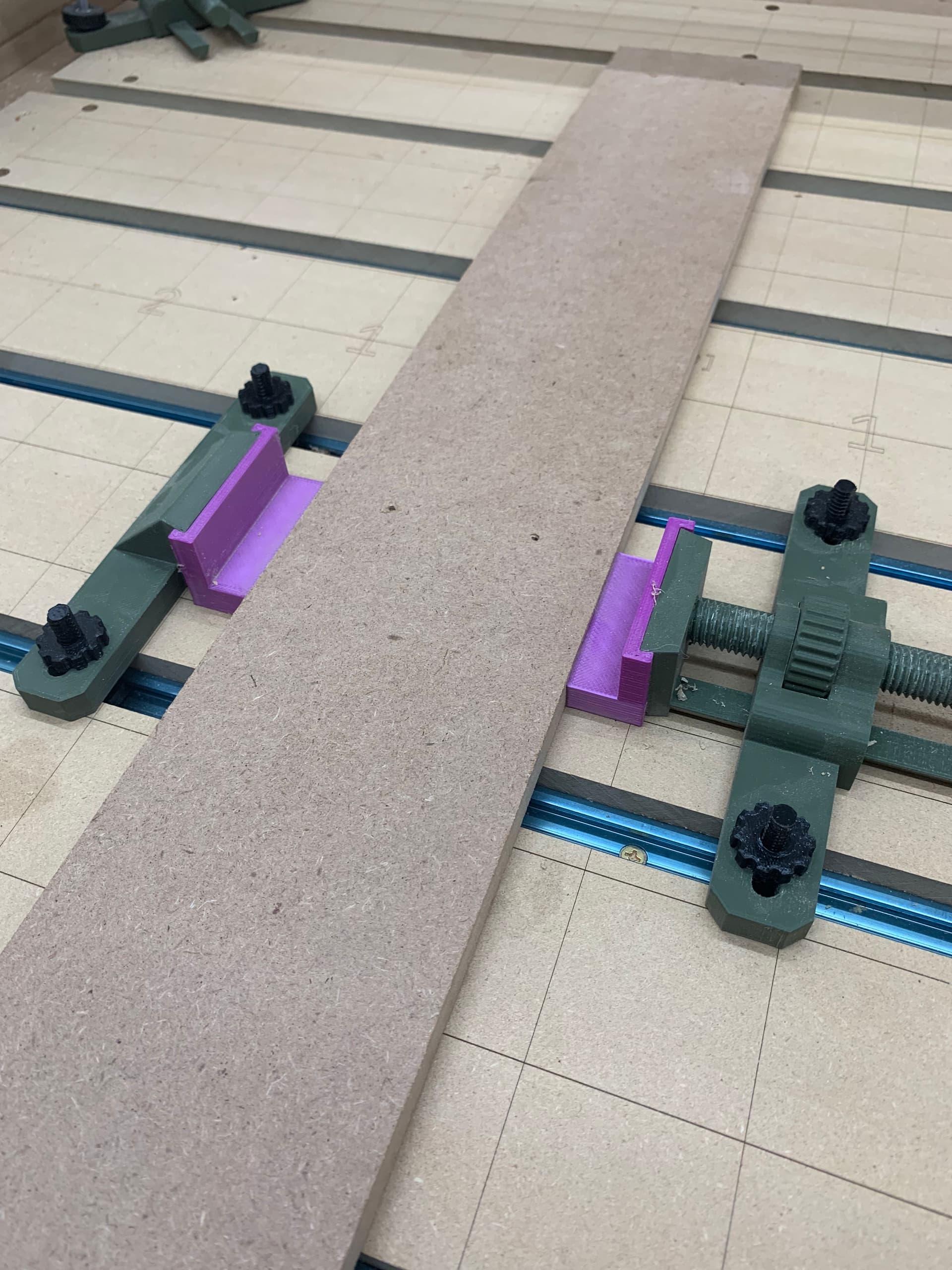
This is one of my old spoil board strips and is about 1/2" thick. You can see I was able to bend the MDF and the part at the clamp stayed put. I’m not an engineer but I think that because the ‘toe’ is below the screw part that some down force is applied when clamping. The piece felt really stable so I printed two more sets of clamps.
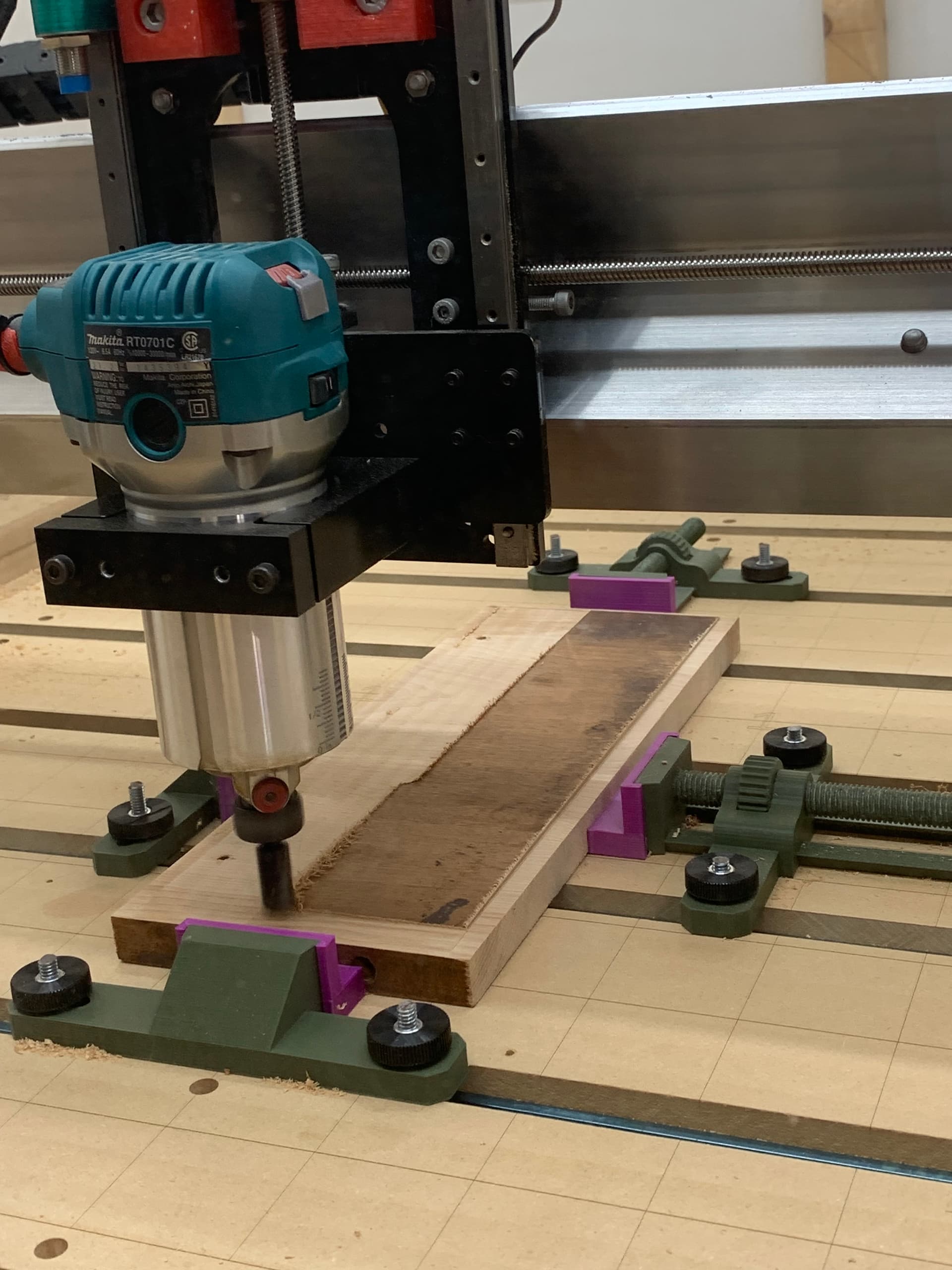
Here I’m using two of them to surface some scrap that came from an old table. It worked great. The clamps aren’t in the way and all the metal bits are well outside the cutting area.
One thing I noticed is that because I used right handed threads my clamps have a lefty-tighty feel to them, loosening the nut extends the screw and tightens the clamp. The files in the zip below use a left hand thread to fix that.
The spacing was also made to fit my T-track spacing but the files are a good starting point if you want to give them a shot. There is file called ‘JawPadCutter.stl’, that file is of a slightly enlarged (0.2mm all around) jaw used to make the cut in the pad. If you design some different pads that should give a decent fit.
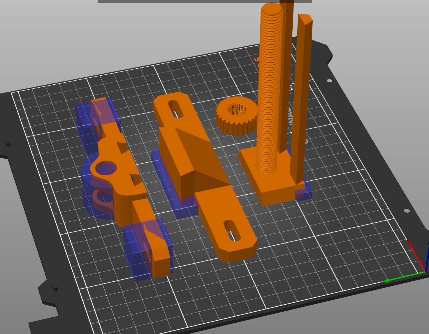
For print settings I used a 0.6mm nozzle with 3 perimeters and 40% infill to up the strength a bit. With the exception of the flexible jaw pads everything was printed with PLA.
The purplish transparent parts are support enforcers for the areas that need support. I learned the hard way that you want to be careful with ‘use supports everywhere’ because it put tiny supports in the threads that I didn’t notice until too late on my first print.
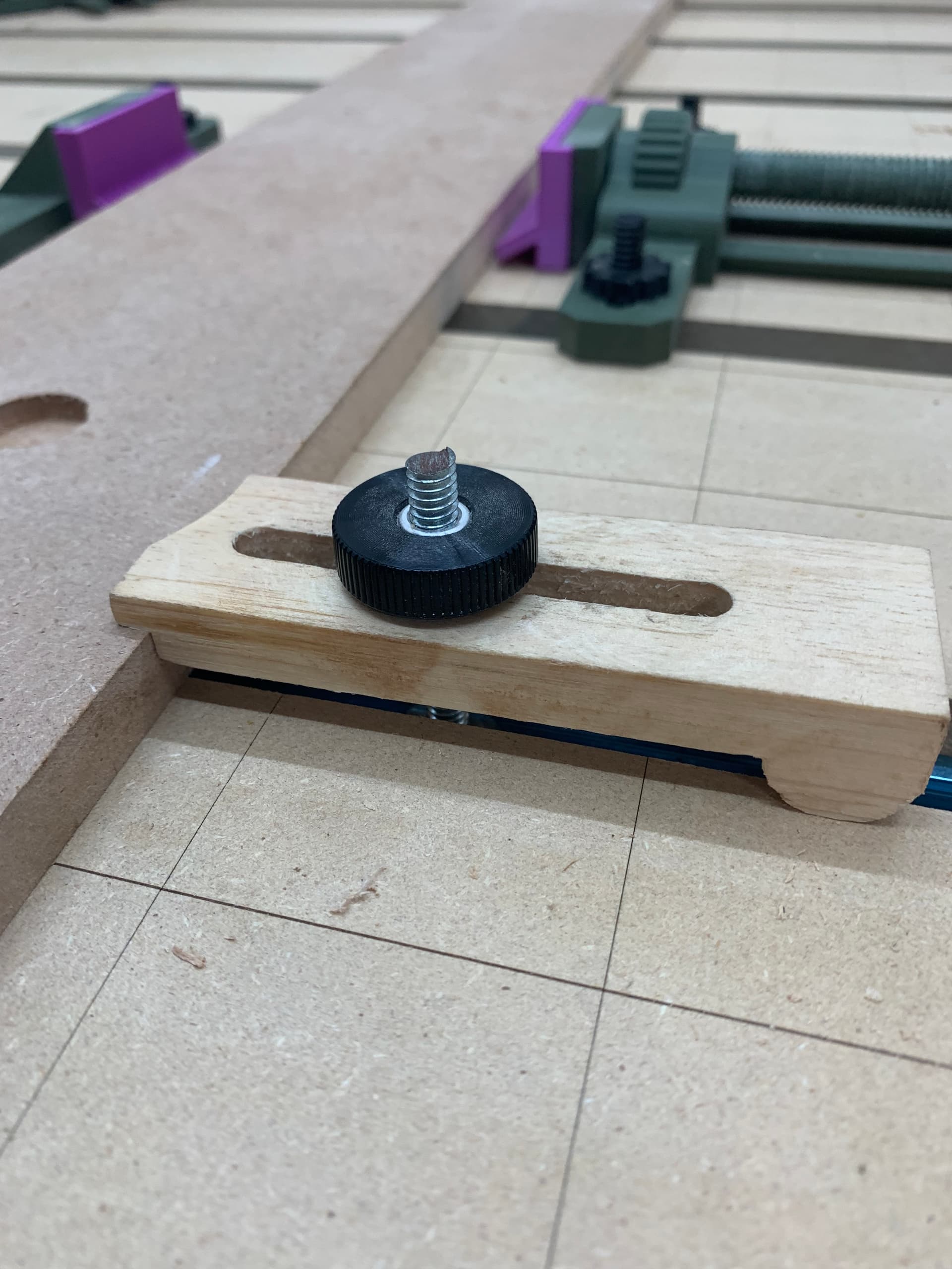
Don’t forget to tap on the surface of the stock to make sure it is in fact on the spoilboard. It is very easy to end up with a small gap between work piece and spoilboard. Use downcut tools (learned the hard way). I have dogholes all over the spoilboard and I use 3D printed pins and eccentrics to apply the clamping force.
That day has a ready passed. I have a few answers, one is to not have time to deep dive into the question, what machine is the best for the buck value. I’ve went under almost 2 years looking into to different mills before going with siencis longmill.
I like to know why not to go with something just by looking at specs and before you get to that point, you’re way into the future. I did a quick looking into 3d printers while diving for mills, and decided not to follow that path for I deemed one steep learning curve bordering against the max I can handle.
The other is budget. When I dive, I look at price range of the high end of the spectrum. I don’t dive merely to have spit dripping into my beard. I dive to come up with the best and go with that. This means that I need to have a budget large enough to at least get a decent machine. No chinese pile of promisses will do. I need to have a feel that the company I’ll go with is to be trusted with me being a client. I will not buy the product if I would not consider working for that company myself.
I did have a budget exceeding the long mills price tagg at least 5 times. I however do not have this financial freedom today.
The last thing I need is to feel the need for the machine. You guys are filling that cup, but I’m not there yet.
I see the why because you are showing that to me, but the other two are not met and wont be for long time.
I am however not less interested than when I took a quick look years back. The lure is strong.
Absolutely love it - I really do find that a 3D printer unlocks extra functionality with a CNC machine.
I will definitely be printing some of these out, once things cool off a bit - my printer is in my unconditioned garage, and the filament really doesn’t do well in this heat!
Not that you asked but 100% my vote is for a Bambu Labs printer. I’ve owned a few different models over the years but a few years ago I bought a X1CC and my life just got easier with it.
I have printed 100’s of models (if not 1,000s) and can count on 1 hand the number of times the printer had an issue (maybe 2 hands for operator malfunction).
Their machines are just plug & play. And I only print in PETG which is nothing for this beast.
Accepted! To be fair I’ve already played with this a bit. I wasn’t comfortable using them with a clamp where the surface the nut would hit wasn’t level. It forces the bolt to bend because a plastic T-nut has to fit tighter than a metal ‘toilet bolt’ in order to be strong enough. My first attempts also used vertically printed bolts. They were pretty strong though, I kept tightening the nut until one broke and the bolt/nut flew up and hit the top of my enclosure 3.5’ up. So I think it had a fair amount of tension when it broke!
Anyway these were printed with the bolts lying down for increased strength. Printed with PETG through a 0.4mm nozzle. I needed to drop the nozzle from 0.6mm in order to get decent threads.
The zip file has the T-nut, who knows if it fits anyone else’s T-tracks, the top nut, a vertical 100mm bolt, a horizontal 100mm bolt, and a 30mm tap that was used to cut the threads in the nuts. With the tap you can design your own T-nuts if needed and the bolts can be trimmed to length in your CAD software.
If anyone needs to make Nuts and Bolts and your CAD software doesn’t have them you can try my OpenSCAD library. It comes with a PDF that should get you going with OpenSCAD if you’ve never used it before. The library uses the ‘customizer’ which is a graphical user interface that allows you to change values and make different parts without messing with code.
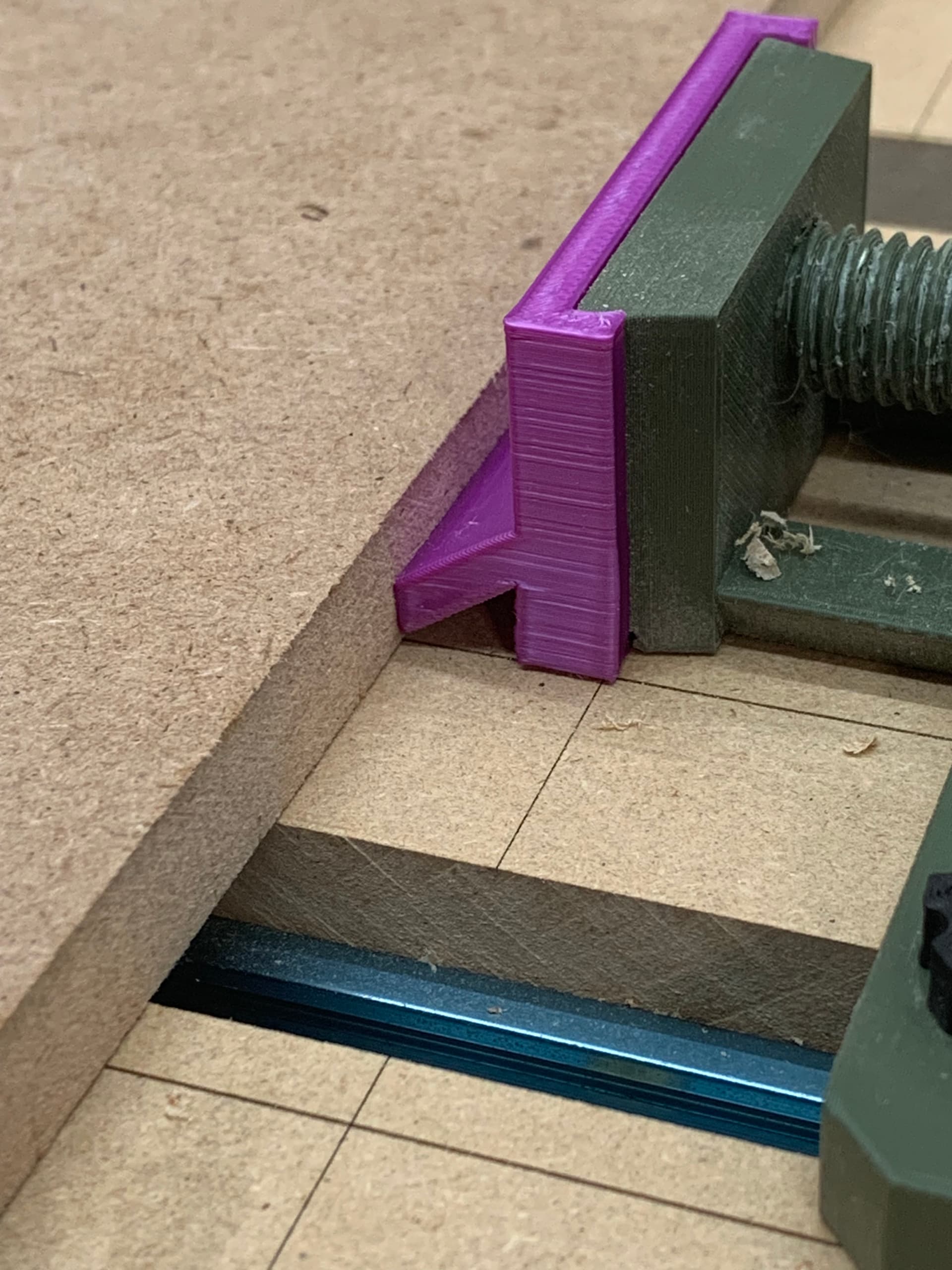
Update! I had another idea for a ‘jaw pad’ to provide more down force. It uses the same principle as a featherboard. I’ve added JawFeatherboard.stl to the OP. The photo only shows one side but I’m using the new design on both sides. It’s working well so far.
Ummmm …. it’s not applying down force. There is a slight bending force on the little bit that connects to the wood and this force is both towards the wood and a bit down from the bending moment but I do not see how you can call that an effective downward force.
If the clamp is stationary and I push on the toe it moves down as it is pushed. How are the forces different if the wood is stationary and the clamp moves?
Also provided there is enough friction you are trying to bend or ‘jam’ the toe the same way a featherboard doesn’t let you back up.
Now I don’t think any type of side clamping that I’ve seen is going to provide the downforce of a clamp that contacts the top surface.
So weather you call it downforce or resistance to moving up this design feels like an improvement but I don’t have the equipment to put any numbers on anything.
Also if I leave a small gap under the board, easy to do as it has a bend in it, the gap closes as I tighten the clamp. Some force causes the board to move down.
There are many commercial clamps that act on the side of the work piece. Every one of these applies the clamping force on a downward angle. In your case the force is applied horizontally. As to the feather board analogy, I do not believe it applies either but I can’t really explain why I believe that. The arrangement you have might apply a minor down force but 99% of the force is applied horizontally.
I have a set of toe clamps that work on an angle. They still rely entirely on friction between the toe and the work. This clamp that I’ve made isn’t any better in that regard. If I don’t need to access the whole top surface I think these simple wooden clamps are superior in every way compared to side clamping.
That one was a little too close to a tool path at least once. With the notch you get extra resistance to being pushed toward the clamp and there is no way my CNC is going to pull anything upward that has those clamps. With all the down force they can apply the friction against the spoilboard is increased to prevent lateral movement as well. Any type of side clamp is only for when I can’t top clamp as I find four of these wooden clamps can hold anything securely.
I’m not sure how to explain the ‘featherboard’ one but I believe some percentage of the lateral force is redirected down. I have no way of knowing how much but I think it’s better than the original that didn’t even try to direct some of the force down.
One more thing. I most often see toe clamps with a fence on the other side. That way only puts downforce on the clamp side. You could use toe clamps on both sides but I never see it done that way. Most likely because it’s hard to position something with toe clamps on both sides. My printed clamp has the same problem as the ‘fence’ side moves when squeezed. I don’t need to be accurate to surface as long as it stays down.
There will be some downward force but it will largely depend on how stiff the entire system is and how much friction you have.
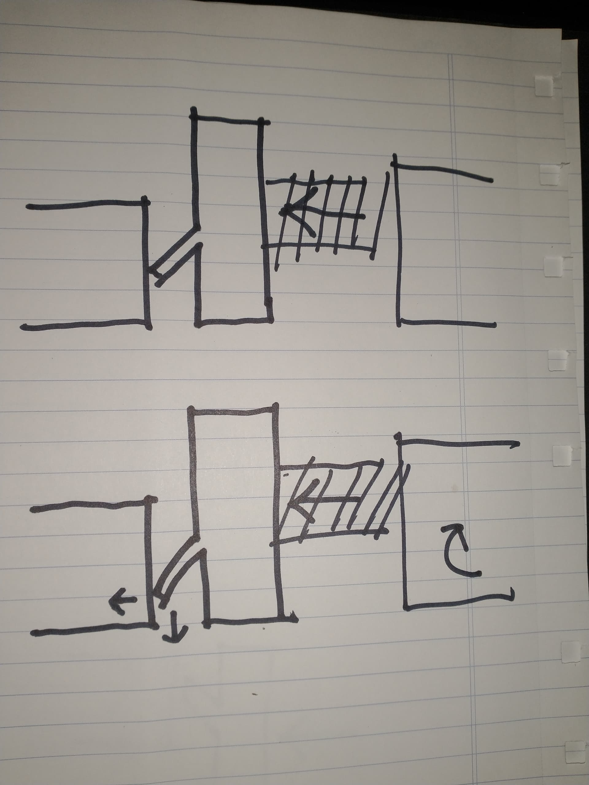
As you’re applying the horizontal force on the clamp, that little “featherboard” feather (for a lack of a better term) will try to deform. As it does, it will push down and out. But that will depend on how stiff the feather is.
That being said, that downward force will be counteracted by an upward force, which translates to a bending moment in the screw and where the clamp bolts to your t-track.
Depending on how stiff your clamp is, you might notice the clamp riding up instead of your workpiece being pushed down.
Like I said, factors like stiffness and friction will determine how much downward force you actually apply. Your second picture shows the clamp body closer to your workpiece than the first picture. That would be more effective in applying any downward force.
@Chucky_ott Thanks for your explanation. Just wanted to say that I only made the clamp extend far so that I could reach clamping perpendicular to the T-tracks. They are strongest when extended as little as possible as you say.
They have decent clamping force, whatever that means, but I can overpower them and pop the work piece out. I can do the same with any of the side clamping systems I’ve tried though. I haven’t tried eccentrics and dog holes but I’m pretty confident that I could rip the board out of those clamps as well. I suppose at some point clamping force is overkill. The problem as I see it is you only find out it’s not clamped tight enough when it fails and your work is ruined and tools possibly damaged.
Top clamps are the only ones I feel truly secure with because they’re the only ones I can’t just make fail. If I’m wrong on the eccentrics and dog holes, and I very well could be, someone let me know. I watched a video recently linked in another thread I think I could remove all the parts he gave a little tug and shake on.
You are correct. The work piece can be removed from any side clamp arrangement with enough force. The secret sauce is to have the clamps apply enough ‘fixing’ so that the work piece does not move. You are not trying to prevent Hulk Hogan (RIP) from removing the work piece.
If it comes down to it, if you try hard enough, anything can be removed if enough force is applied. Top clamps are inherently a stronger hold down but if you need to surface the top that doesn’t help you.
BTW, an improvement to side clamping is to cut a ‘step’ into the side to provide a more secure clamping force then what a ‘step-less’ side clamp can provide. Think of a groove cut all around the work piece and you use your top clamp on the groove instead the top. You get most of the benefit of the top clamp and can still surface the actual top.
@Chucky_ott - THANK YOU for putting words to my thoughts. This is exactly what I was thinking even though I lacked the words to explain it.