While I am nowhere near being able to worry about vertical milling on my Altmill, I would like to run an idea up the flag pole …
On the Altmill, when the spindle is all the way forward, it is very close to the front edge of the table. I have noticed that the spindle clamp has 4 holes on the outside front which I assume are for mounting a laser head. I am wondering if it would make sense to fabricate a mount that attaches to the spindle mount for a secondary router. When mounted in that position, I would expect the center of the new router shaft to be maybe 3" to the front of the current spindle. If we assume that the current spindle is 0.5" from the table edge and if we further assume 1" being used for a vertical work holding device of some kind, that would leave maybe 1.5" of material thickness that could be routed. Does this make any sense?
I am thinking that the gantry on the Altmill is plenty strong as long as one doesn’t get carried away with the kind of cut that one attempts to do in this over-hanging situation. Yes, there will be a bit more flex but again, if smaller cuts are taken, will this be a problem?
Anyway, I am soliciting thoughts on doing this - is it totally nuts, slightly unhinged or is this worth a try?
That is true but keep in mind that Sienci was experimenting with a 4.4kW spindle and that would, IMHO, be way heavier than having a smallish router attached. I have no doubt that the weight will be manageable … I am more concerned with having the weight hang off axis as well as possible vibration due to flex.
Of course I might be way off base with all this so please keep the thoughts coming.
Yes, that is what I call ‘vertical milling’. Every configuration that I have seen involves a cutout in the mill’s table and the board to be milled is held by some kind of fixture under the table. It would seem to me that having that fixture at the end of the mill table makes the entire operation easier.
There have been versions of Long Mill machines that have the vertical hardware at the very front but in those cases the effective area available for traditional work is reduced.
ah yes, well vertical milling is sometimes refered to as mounting the complete machine vertical.
I have my mill on a slab of mdf, resting but not mounted to my table. I’m still on the fence about cutting out a piece of mdf at the front so I can slide the hole mill over the edge of the table and do the vertical thing. I have not encoutered the need to do so, so I have not implemented that option yet…
Your solution surely is novel and I always like out of the box thinking. You might wanna try and mount some dead weight at the position you envision your extended spindle to go, just to see if the machine can handle that extra weight that far out. it might put a fair amount of strain on the various components that may cause extra wear.
keeping a weight tight to your body is way easier than holding it at arms length. Maybe opt for a small palm router as your vertical mill unit?
Someone had another novel idea on mounting the complete spindle vertically to be able to handle longer stock. maybe look into that idea aswell?
But looking at the Altmill and it’s table frame I guess you need to either go all the way in front or use a space between the framing. As far as extending or moving the router 3" forward, I would think that if you slow down to compensate that it could work. Bear in mind I am not an engineer, not by a long shot!
I tend to work with lower feed rates when I use my vertical setup especially when using a dovetail bit because they need to cut full depth in one pass.
I don’t use my vertical mount on every job so it’s not really a problem for me to remove one section of my spoil board when I need it. I suppose if you are doing a ‘sea of holes’ type of spoil board instead of T-tracks it might be less convenient.
My thought was to go all the way to the front of the frame, an area that the regular spindle can not access. This would be just in front of the Altmill’s front cross member. That is why I was thinking of mounting a secondary router in front of the current spindle when the job calls for vertical milling.
Yes, I would reduce the feed rates because this would be a router instead of the main spindle (less powerful) and because of the position further out from the normal spindle position (less rigid). I would probably not do a single full depth pass but I would use a straight mill to clear out the middle and then use a dovetail cutter to do the final cut. Actually, my thought had been more in the lines of a finger joint which of course can be done with multiple depth passes.
So far nobody has called me totally out of my mind so I think it might be worth a try to build a prototype of this setup. I would probably 3D print the initial mount to see how this concept would work.
While the official work holding setup would be for a straight vertical setup, if it works out, I might incorporate a tilting work setup system so that I can run 45 degree angles.
I was wanting to do something along these lines myself. Was thinking more to move the table back to the previous cross member and leave the front open, but that gives up a lot of the table, and the main reason I bought the AltMill to begin with.
But I have a small 24-48v spindle with an ER11 collet, that would probably be perfect for hanging off the front since it’s nice and small. I wouldn’t need anything big to cut tenons.
Hmmmm, I may have to work on this at some point myself. But for now I have plenty of projects I can do before I need more to do.
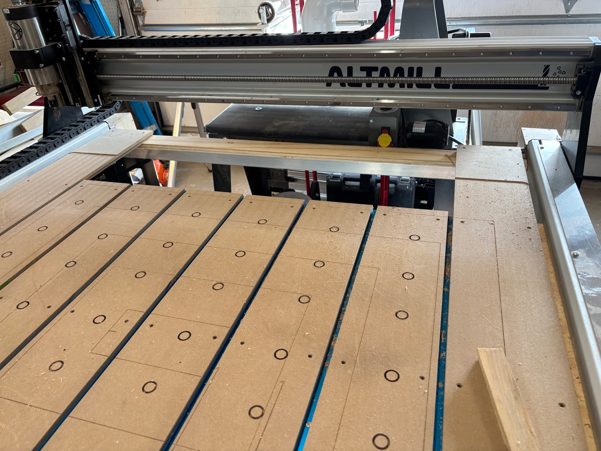
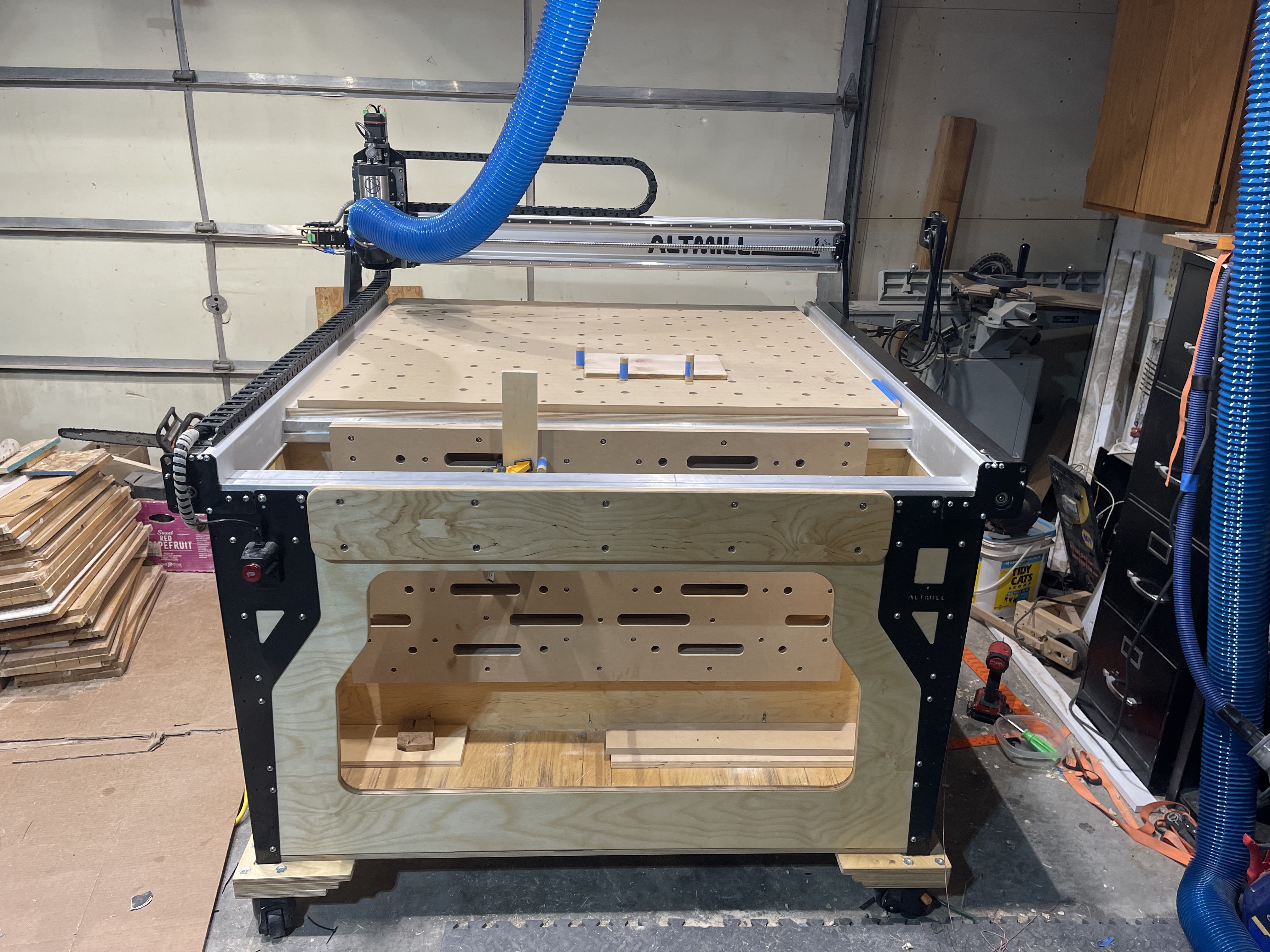
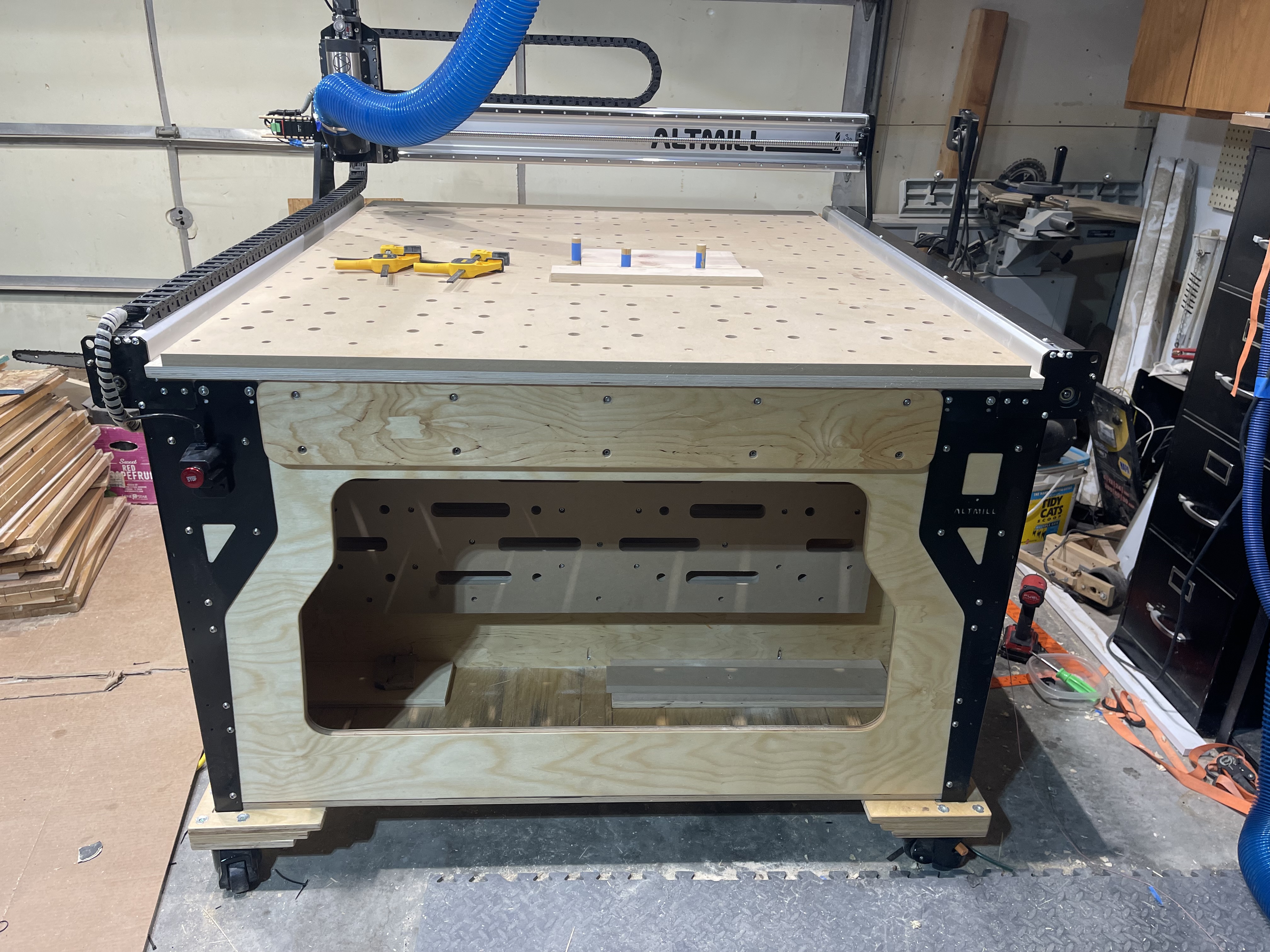
During assembly of my Altmill and the wasteboard I decided to stop the wasteboard at the second cross member from the back of the machine. I have 6" in Y available and 48" in X available for clamping material vertically. To maintain full Y range and the possibility of tiling longer material I will have a removable piece of mdf that can be attached over the back rail for support. Removable so I can flatten it as necessary when the wasteboard is resurfaced. The two pieces on both sides of the Y axis will be removed when I venture into that phase.
Just lose the legs and the last cross piece. Build a table with drawers and storage just like you would for a Longmill. Have a notch at the end of the Y axis a few inches in where you install your vertical clamping surface, complete with grooves or t-tracks or whatever you want.
Interestingly the Shapeoko 5 Pro has an alternative mounting position for the gantry that puts it 3.2" out over the end specifically for joinery and vertical milling.
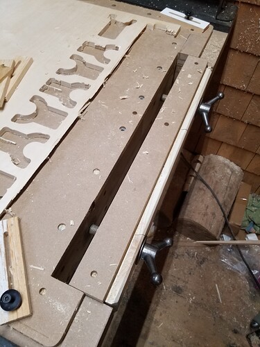
I set my Onefinity table with a means of doing vertical milling. I’ve used it to do box joints and also made a mortise and tenon.
I haven’t found it to be that useful though. These kind of joints are better and easier to do on a table saw.
So, in my opinion it’s not worth setting up your CNC to do these cuts.
I love the idea of vertical board off the front with a bench end vise. As much metal as the factory spindle mount is I bet it would extend ok. I wrapped my vertical board up last week. Contemplated putting it on back but didn’t wanna work between motors. Just put it between first and second cross members at front. Working on a way to secure the extended waste board that covers the vertical board.
That clamping surface looks like the ones that the Avid people use. Seems like it should work fine if a little awkwardly.
I’m not a carver, furniture and cabinetry are my things. So joinery is a big deal for me. I think of the Leigh FMT and the Shaper Origin on it’s little workstation as models for this kind of thing.
My idea would be to lose the end cross brace or move it in 4 inches or so. (Of course I’d wait 120 days before tinkering) I probably won’t use the legs at all. I’ll put it on a cabinet. From what I can see that’s almost what you did.
Incidentally, how do you like those ratcheting castors? I put some on a welcome booth I built for my church. I have 5 on it because it’s curved but they’re carrying about 400 pounds.
I honestly don’t see why you couldn’t leave front cross member out. Specially when building alternative frame for vertical board. The casters are ok, Small wheels don’t roll the best but nice big feet and I like that. I feel like that fits the bill, I don’t wanna move it I just want to be able to if needed. I did have some where the ratchet just does not work. Out of 8 I had 2 fail. They returned them tho. Hot new ones.
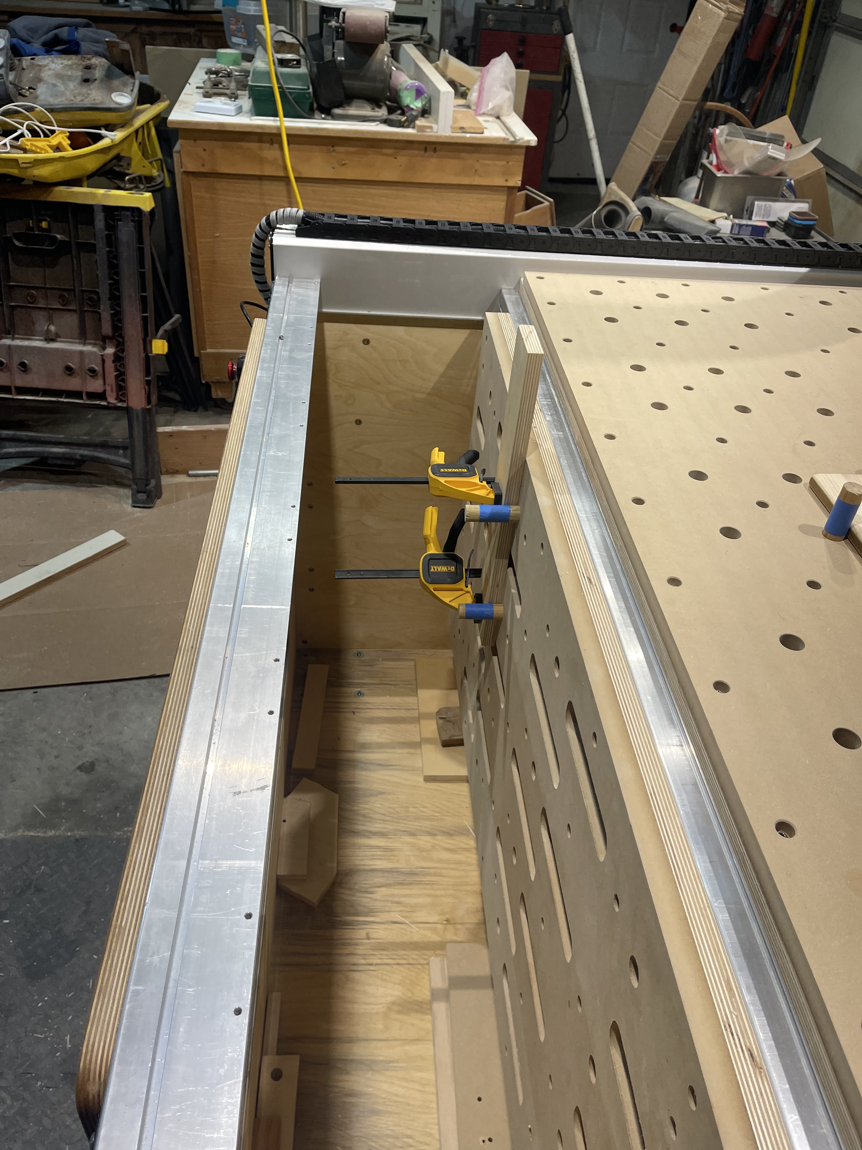
Progress picture - slow but steady …Mounted on the front cross member using the T slots in the cross-member which required some out-of-the-box thinking. Spacers were used to locate the drop-in nuts and teeny tiny wedges were inserted behind the nuts to keep them in the correct position (they flopped all over the place before). With the drop-in nuts located and wedged the vertical board went on perfectly.
In the picture the router is located about an inch in front of the mounting board with lots of room for thicker stock. Width of the board is the width between the leg angles.
Have you discussed your approach with an engineer (perhaps someone from Sienci Labs?), as I’m a bit leery about the additional stress on the gantry and Z-axis components resulting from having milling operations - even paying attention to going gently - outboard of the main mount.
If the engineer gives you the green light regarding the torque issue I raised, then perhaps a better approach would be to have a new spindle mill made, which holds the spindle in the position you’re having your secondary router positioned. Thoughts on this?
Incidentally, I was about to cut a slot into my table before you came up with this intriguing idea for mounting the milling system ahead of the existing mount..