I uploaded the file to Thingiverse here: https://www.thingiverse.com/thing:7133096
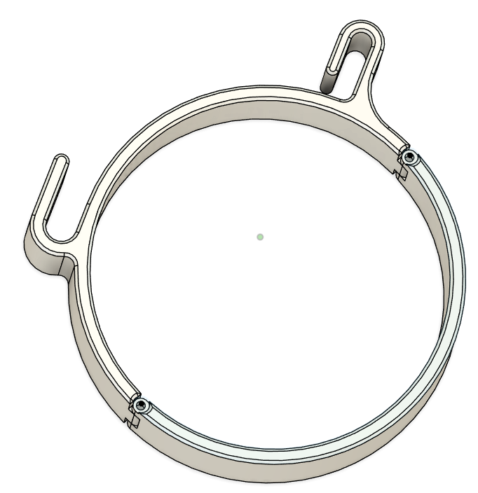
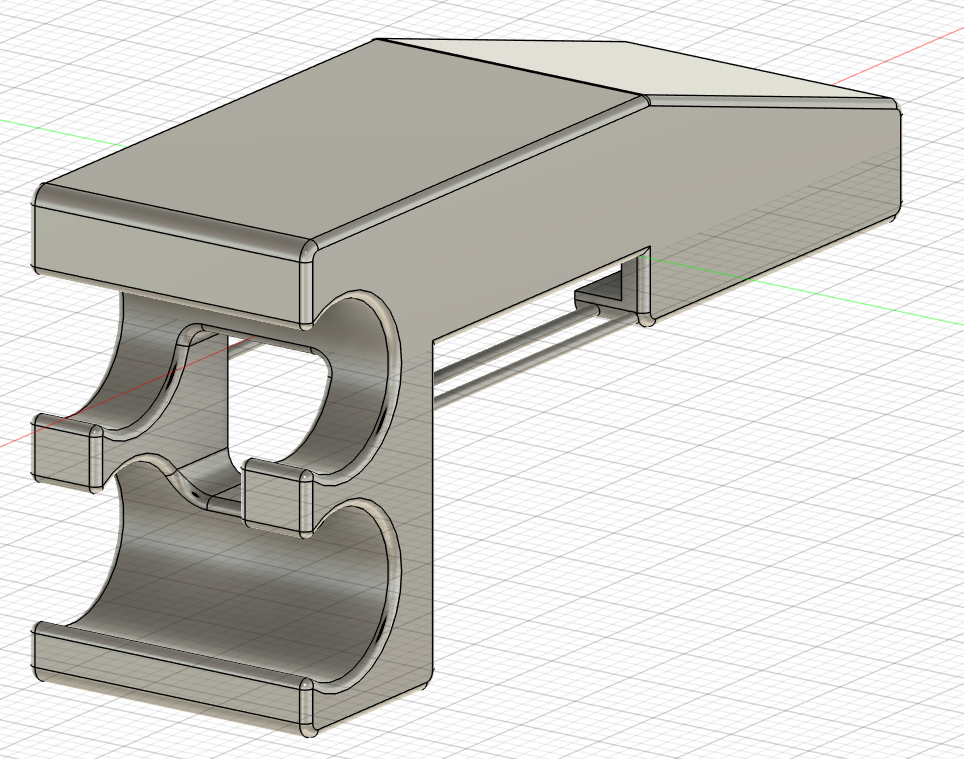
I should have mentioned I made it two halves to make them easier to put on, but the hose does slide through so it could be easily made into a single solid part. It is modeled for M2.5 bolts, but you can stick a wire through, glue it, etc. instead. If you want a solid one I can easily adjust it. I uploaded a .step file to make it easier to remix for others.
Instead of adding sliding complexity for screwdriver access from the side, simply extrude a small round perpendicular hole thru the bottom hose clip for a screwdriver to reach straight through.
The hole only needs to be big enuf for the screwdriver, and - depending on exactly where it aligns between the 2 hoses - might not even require a hose to be unclipped for access…
1 Like
This is a good idea as well.
What kind of coolant are you running? It has a slight blue tint is it windshield washer fluid?
@JPlocher That’s a good idea…..but…the sliding aspect would be necessary if the drag chain was installed with the hinge side on the inside of the mill. In this case, you’d have unfettered access to the screwdriver slot, but you would not be able to lift up the clip without sliding the tube holder first. I can still put an access hole there, but I’d leave the t-track as it is now. It doesn’t hurt anything and the tolerance for sliding it have been solved already.
It is a light mixture of automotive antifreeze (I used 50/50 premix and cut it about half again with distilled water). Figure it is both easier to see and apparently has corrosion prevention and lubrication qualities over straight water. Not worried about freezing 
1 Like
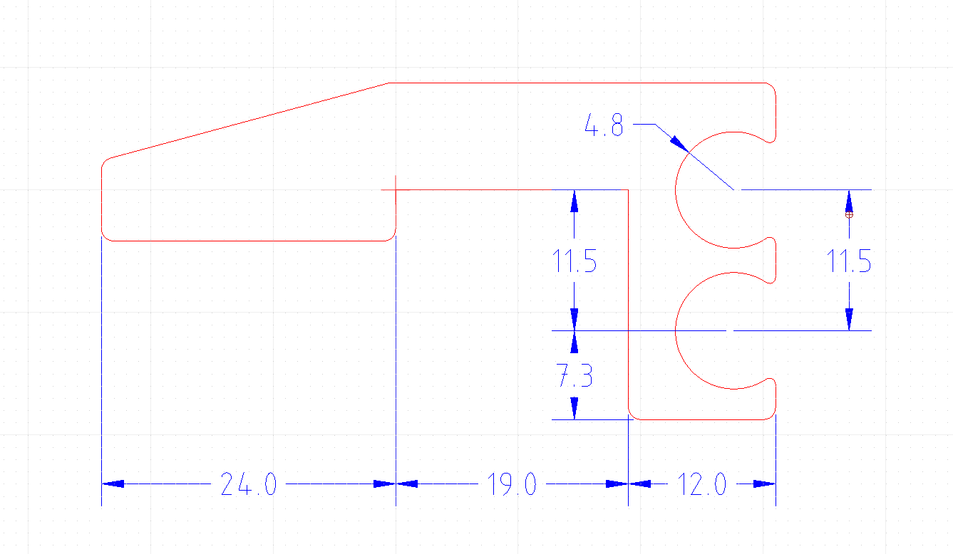
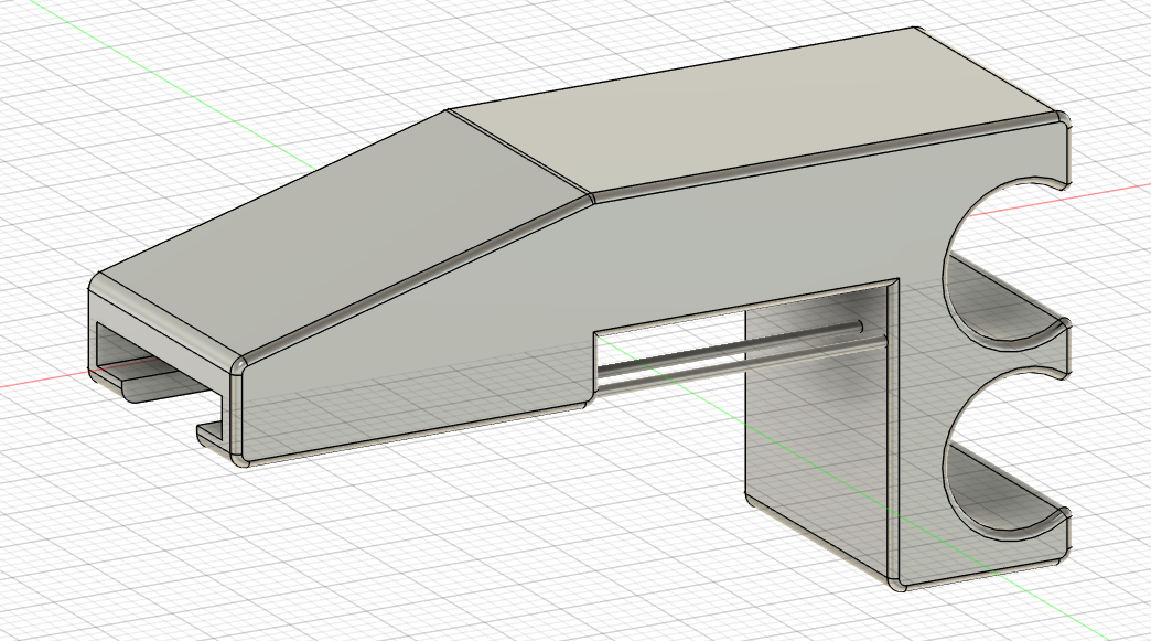
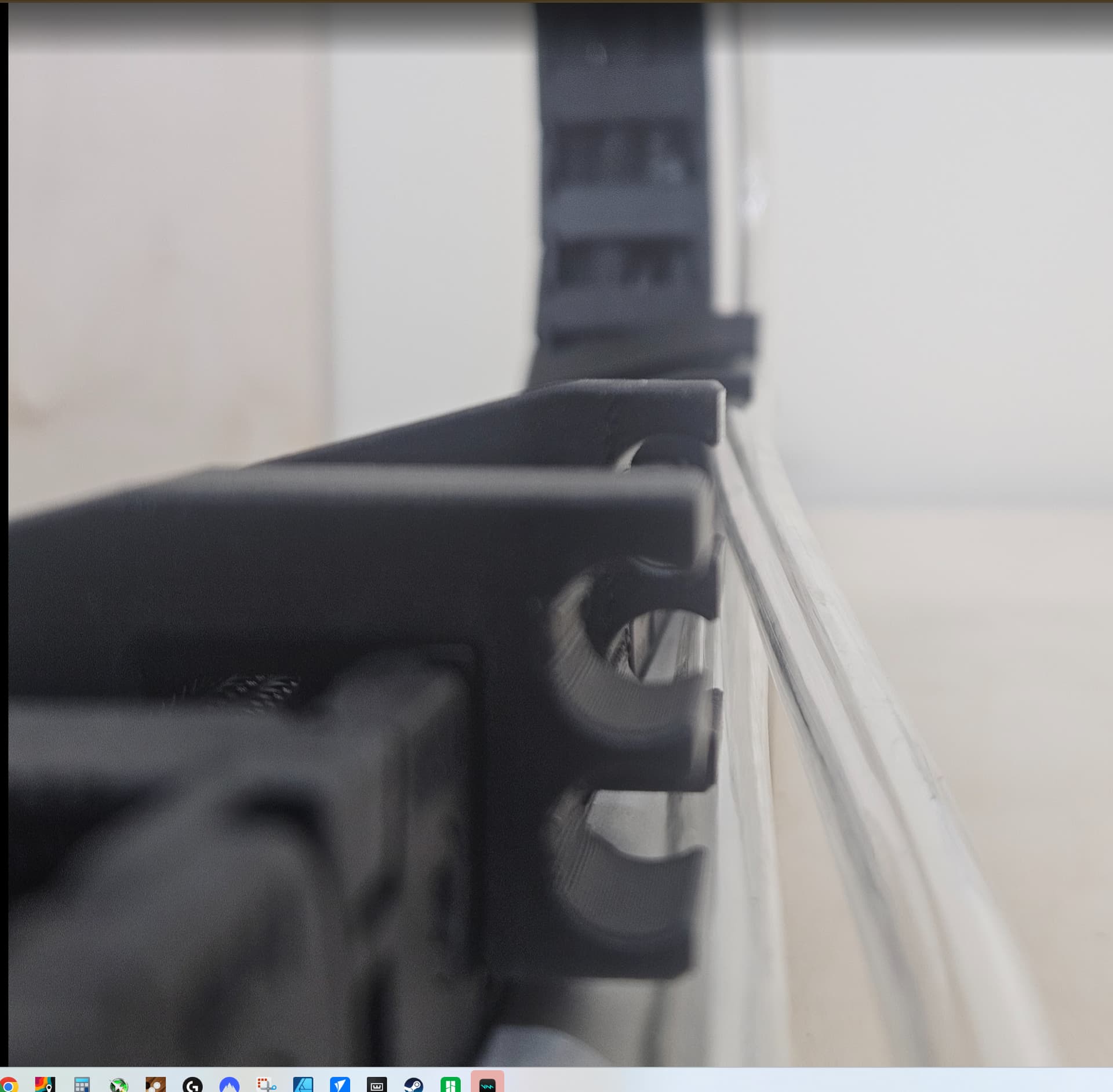
@Headshop Here’s v10 with the bottom tube exactly at the pivot point of the drag chain. The top tube is slightly above it. I kept the diameter of the hole the same for a snug fit as per installation method in post #81 ( Any 3d modelers out there - #81 by Chucky_ott ). I got rid of the little extension at the front since it has no purpose. Key dimensions are as shown. According to my measurements, the bottom of the tube holder should clear the top of the y-rail.
Tube_Holder_v10.stl (901.5 KB)
1 Like
Thanks! Going to print a few of these and run a test compared to the old version 8/9 one. Ill get back to you on how they perform
your post had me going in all kinds of directions! ultimately ill probably go with a distilled water and pray for no long duration power outages. Or maybe even an RV Antifreeze Concentrate that I will mix with distilled water!
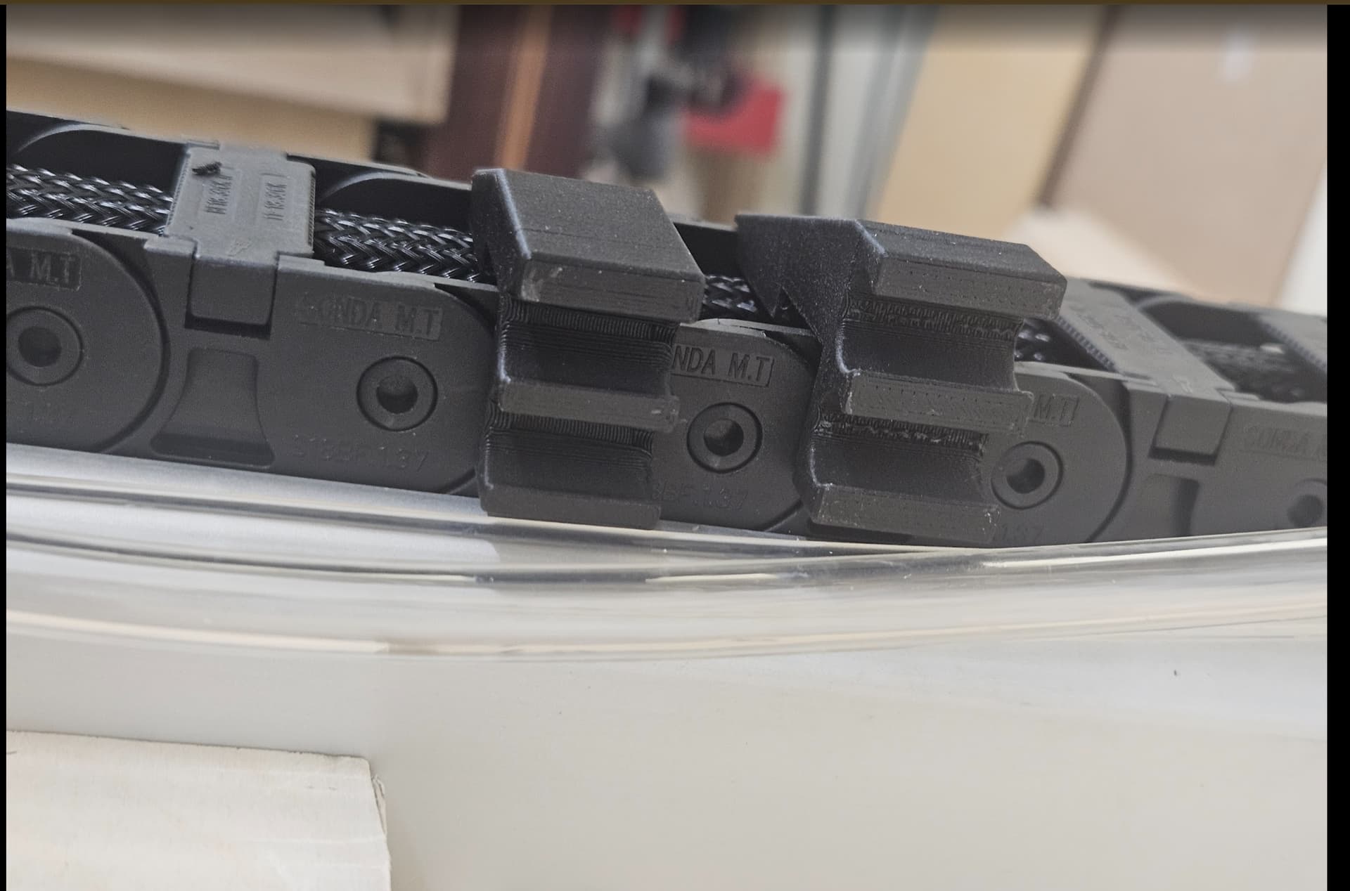
printed 4 of them and they are better aesthetically and probably functionally. I was impressed enough with the new design that I’m printing another 8 to give these a try to see how they perform compared to the last set. Getting rid of that slope really made them look less stuck on and more like they are a part of the chain and meant to be there. The slot for access to the clip still might be a good idea. It would have to be atleast 7 or 8 mm wide and probably that tall as well. As I’m sure you are aware releasing the clips is more of a twisting motion instead of a prying motion,
@Headshop ok. I’ll put a 8mm hole right in the middle of the two tubes or at whatever distance centers on the screwdriver slot. I’ll go do that now.
@Headshop
@JPlocher
The center of the square hole is 6.5mm down from the top of the chain.
Tube_Holder_v11.stl (1.1 MB)
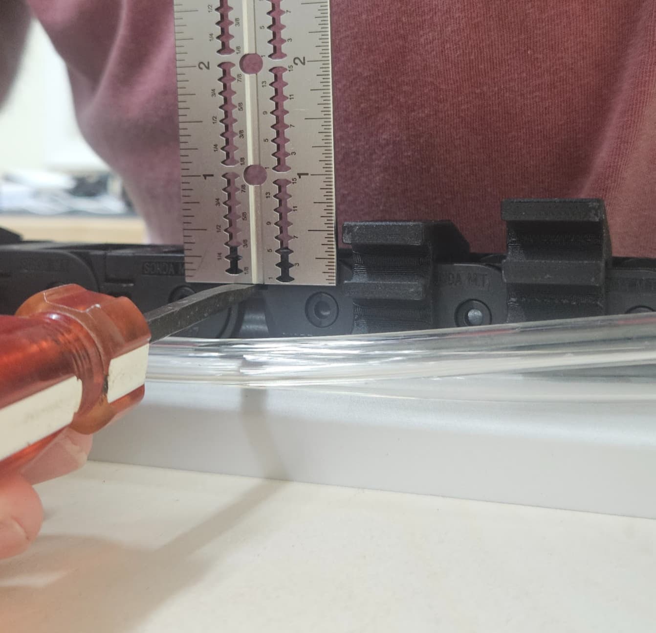
Cool.. here is a photo that was very tough to manage showing a very good representation of where the center of the slot aligns to. Now granted the bottom of the ruler is on top of the slot the screwdriver is in. So maybe drop it down a half a mm or so to get even with the center of the release slot?
actually looking at the photo the center is probably IS the middle point between the two tubes
Oopsies. I was measuring the hinge side. Slot on other side is a bit lower. I’ll update the post above with only a square hole a bit lower down
Printing v11 sample now. Ill let you know if the hole placement is spot on or not as well as hole size.
With the hole in the center those are now tricky little things to print! I finally got it to print correctly after the third try. I had to make sure there was plenty of glue stick for those tiny little feet in the middle to adhere to something properly. As far as how it work, it works flawlessly once printed that is. Is it too much to ask to making the hole 1mm smaller on all sides. Id like to see if my screw driver will still fit in and is able to twist the locks open.
plus making the holes smaller with make the little feet in the middle larger making it that much more likely to adhere to the build plate.
@Headshop Here you go. I only decreased the width from 9mm to 7mm. Decreasing the height would not change the "feet "dimensions. I can remove the rounded edges as well if that helps. Their radius is 0.5mm
Tube_Holder_V12.stl (1.1 MB)
1 Like
That was perfect.. Printed correctly on the first try. And those middle legs are a lot stronger now. Printing 11 more and will install this evening