I’m new to CNC routing, but I’ve been 3D printing for 15+ years.
I just purchased an Altmill 4x4. I’ve done a few projects with it so far (relief carvings and some acrylic inlays) without issue.
My wife wants to make a detailed flag carving for her dad, so I setup a quick test project. She wanted to make it around 10 inches wide, so I mostly set this up to see how the stars would come out since they were so small at this scale.
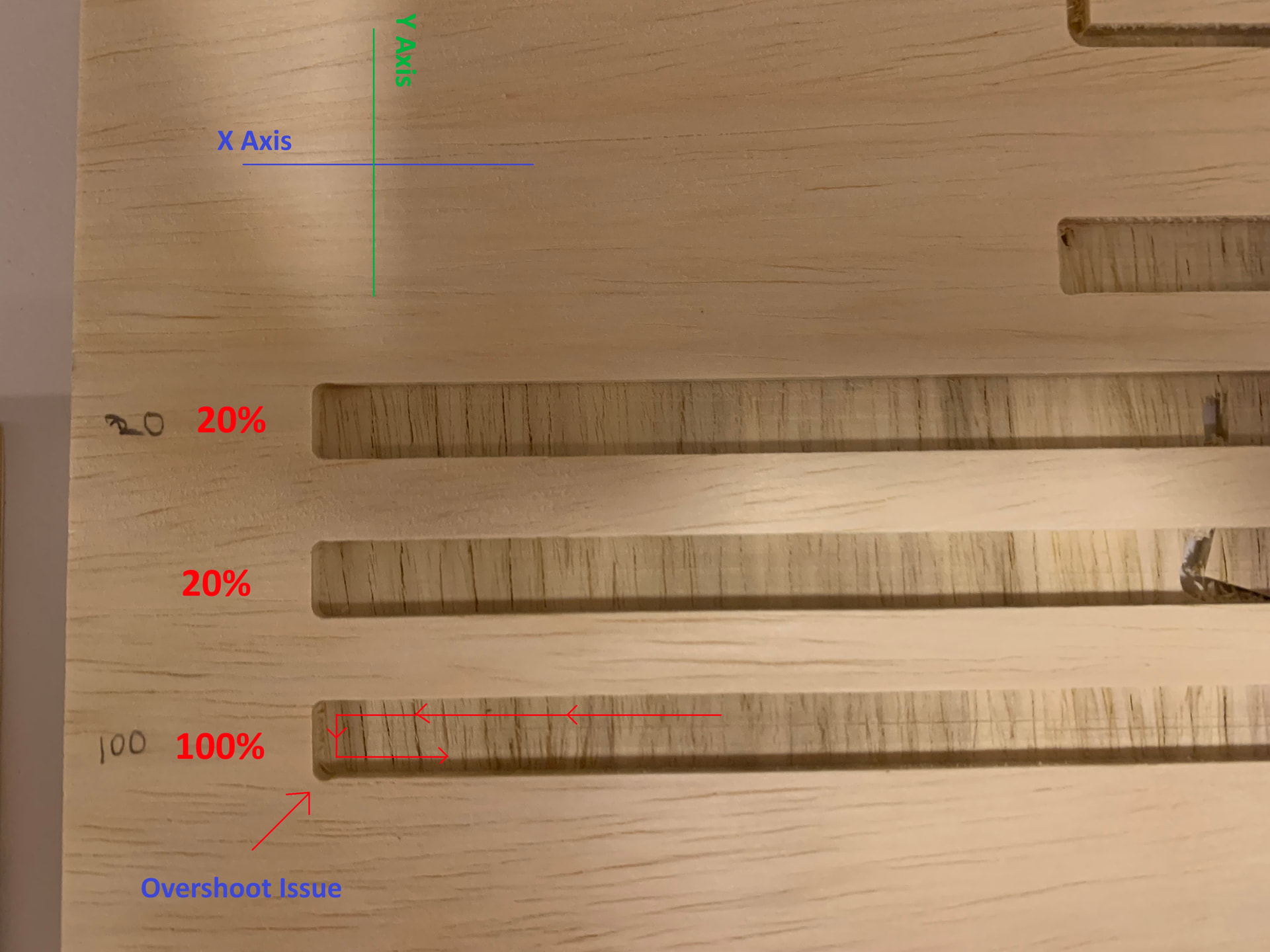
We ran the job, and noticed these “lobes” on the bottom left of the pocket in each stripe. See the attached photo for more detail.
The toolpath for the stripes is a 1/8” SpeTool DownCut Bit (W04006). I imported the SpeTool Database into VCarve and used the settings for soft wood. The toolpath VCarve generated shows a speed of 115” per minute.
I decided to do a second test and let the first stripe run at 100% speed, then slow it down to 20% in GSender when it got to the second stripe. This “fixed” the issue. My immediate thought was to get back into VCarve and dig into the speed / acceleration / etc parameters. I quickly learned that VCarve / CNC routing is not like 3D printing Not much to adjust.
I did some searching here on the forums and online. Mixed results, I’m not sure if I need to slow things down or if it’s potentially a backlash adjustment issue?
Going back to some of my other “hello world” cuttings I can see they have some minor overshooting as well, but not as noticeable as these.
Ah, and the wood is just “Sande plywood” from Home Depot. We just got a 4x8 sheet to test / learn with since it was really cheap.
I tried to notate the photo to show the direction of travel and X / Y axis.
Welcome to the forum , glad to see your jumping right in. There are probably a lot of people here who have experienced this problem. As you know CnC’s are different then the 3d printing you have been used to. I am sure some other people here will be able to also chime in on how to fix this. But on my behalf here is an opinion. Based on your description and the photo, you’re experiencing a common CNC phenomenon known as corner rounding or as you have called it, overshooting. This occurs when the machine’s physical inertia prevents it from making a perfectly sharp change in direction at high speeds.
Because the “lobe” is appearing at the bottom-left corner where the tool transitions from its X-axis travel into its Y-axis movement (or vice versa), the machine is essentially “taking the turn too wide” because it can’t decelerate and change direction fast enough at 115 IPM.
Why slowing it down “fixed” it
By reducing the feed rate to 20% in gSender, you lowered the velocity to roughly 23 IPM. At this slower speed, the machine’s existing acceleration settings are sufficient to allow it to follow the intended path accurately without the momentum “pulling” it past the corner.
Recommended Fixes
Since VCarve Pro does not directly control machine acceleration (it only provides the “instruction” for the path), you have a few ways to address this:
Adjust GRBL Firmware Settings: The AltMill uses GRBL-based firmware. You can fine-tune how the machine handles corners by adjusting the Acceleration ($120 for X, $121 for Y) and Junction Deviation ($11) settings directly in gSender’s console or settings menu.
Increasing acceleration allows the machine to speed up and slow down more aggressively, which can sharpen corners but may introduce more vibration.
Lowering Junction Deviation forces the machine to slow down more for sharp corners.
Lower the Feed Rate in VCarve: If you don’t want to dive into firmware, the simplest fix is to lower your “Cutting Parameters” for that 1/8" bit in your VCarve Tool Database. Try a feed rate closer to 60-80 IPM for highly detailed work.
Use a “Clearance” or “Rest Machining” Strategy: Instead of one fast pass, run a roughing pass at high speed leaving about 0.02" (0.5mm) of material, then follow with a slower “finish” pass to clean up the edges and corners.
Lastly I did wonder what your machine looks like. Have you stabilized the frame? There are holes pre cut for a wood 2x4 or anything else you want to use to strengthen the frame and reduce the bounce of the table.
Hope some of these suggestions help, and again Welcome.
“This occurs when the machine’s physical inertia prevents it from making a perfectly sharp change in direction at high speeds.” - Yeah, just watching it run it doesn’t seem physically possible for it NOT to overshoot. The entire mass of the gantry, side plates, and Z assembly are in play when it’s moving on the Y axis.
I had not yet “stabilized” the frame when we ran it this morning. I spent a couple hours running the two levels of 2x4’s around the machine, then added diagonal bracing between them on the Y axis (sides). It is VERY rigid / stable now.
The photo is from the post-stabilized run. The results were identical, though the machine was MUCH more stable while running.
I looked for a guide on checking backlash while I was still in the shop this evening. What I found seemed to suggest there was nothing you could adjust on ball screws? I’ll check and see if there’s any wiggle in the gantry when the motors are engaged tomorrow.
I’m so accustomed to sorting these things out in a 3D printer slicer (per job). I think part of this is just confusion on my part. I had done several somewhat complex projects right from the start (relief carves in wood and some super small acrylic in acrylic inlays that fit perfect), and what VCarve gave me worked well. Then when I tried to do what I thought was a “super simple” project, I ran into an issue.
I set it up with 4 toolpaths. I have a “cleanup” run for the stripes that uses a 1/16” bit to sharpen the corners. I could have left material and let the 1/16” bit finish it off as you mentioned. I’ll redo the project with this in mind.
@AshleyWilliams Some good suggestions from @Karver_One . The easiest would be to lower the feed rate in vCarve. You do that when you configure the mill you will use. Note that there’s a science behind feed and speed selection. The goal is to maintain an adequate chip load. I don’t have enough experience to guide you further but you might want to read up on it.
@AshleyWilliams Is your test a pocket toolpath?
Did you set to raster or offset?
What is the length of that 1/8" bit outside the collet?
Note, that when you move to the actual project, a pocket toolpath will not be optimal for the stars.
ISSUE RESOLVED: It was the Y axis ball screws. You leave the screws loose initially on the Y axis linear rails and ball screws. While I did come back and carefully tighten the linear rails (the part I was most nervous about), I did NOT tighten the ball screws.
I can’t believe I missed a step but I did, particularly here as the linear rails and ball screws were the parts I was so careful with.
I think Karver_One had mentioned pulling on the gantry while the motors are powered and see if there is any slop. That is what did the trick, when I grabbed the gantry and pulled, there was indeed slop. Quickly found the source of the slop was the untightened ball screws.
Redid the test, no more lobes, and it is indeed completely capable running this particular test at 115" per minute.
Lesson learned - Check, recheck, and recheck again.
Oh this is very wonderful and I am so happy you found the problem. As I say: CnC is not just a hobby… its Art =)). Okay where’s our bumper sticker makers.