Having recently mentioned belt tension in the category of Add-ons & Modifications, I thought it may be useful to detail the method which I now use to tension my drive belts. I know that many of you will use the Long Mill machines which have lead screws. Some people may just be using gSender with their own CNC machines. Others may use 3D printing machines that are often driven with belts so this small write-up may be helpful.
My machine is a standard sized Shapeoko SO3 and it was provided with NEMA 23 stepper motors driving X, Y and Z movements via Gates GT2 belts. Each extrusion is 600mm in length, giving a working envelope of 406 x 406mm (16 x 16”) and a Z height travel of 95mm (3.7”) There is a little extra belt required to thread around each stepper motor belt pulley.
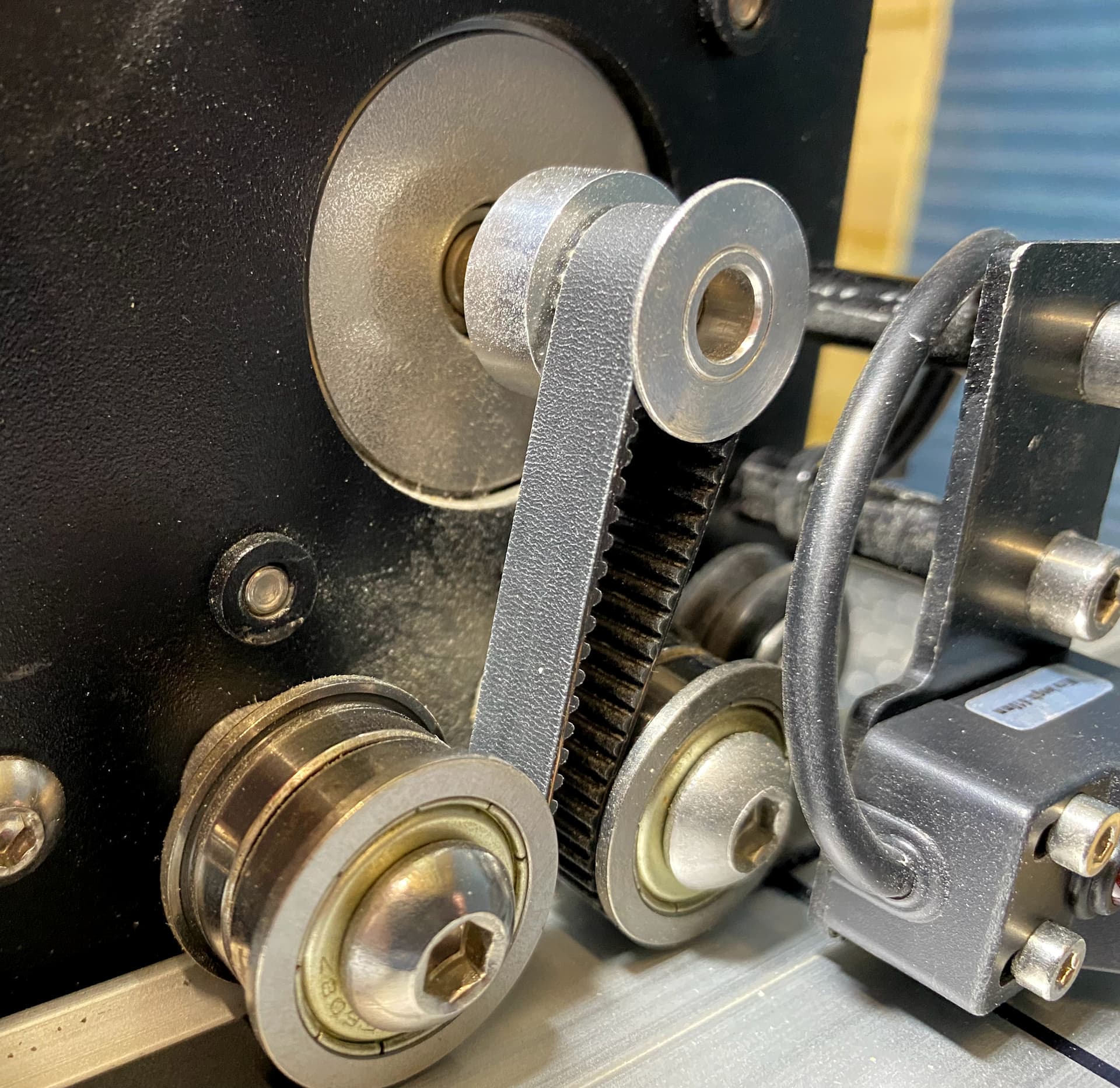
Path of belt around stepper motor pulley
The tuned part of the belt was 280mm in length. The part of the belt to be tuned was raised on ¼” wooden supports. The belt was plucked with a wooden plectrum to standardise its vibration characteristics. The vibration was measured using a guitar string tuner attached to the extrusion endplate.
Supports under section of belt to be tuned.

The short video clip demonstrates the technique. Gates GT2 belts are designed to operate at a tension of between 100 and 150Hz when plucked. I chose a value of 135Hz because it equated to a note of C3 on a vibration sensing guitar tuner. Keeping the belts tuned to a set frequency means that each belt can be set to the same frequency and even movements can be expected. This in turn leads to accuracy of cut and the belts last much longer. The pull on the stepper motor shafts is known and within permitted limits.
ultra short video clip:
The science of belt tension was beautifully explained by Liam Newcombe over at Carbide 3D and can be found here:
The supporting video can be found here:

The belt tensioning clip on the Shapeoko CNC machines was not an easy thing to set up. The belt had to enter the clip at the slot nearest the front of the clip (part nearest the centre of the extrusion) from underneath. The belt was then looped over a piece of metal and pushed downwards through the rear slot. To complete the threading operation, the belt was folded back on itself underneath the belt clip and the remaining belt so that the teeth were now against each other as the folded belt was now 180 degrees away from its original path.
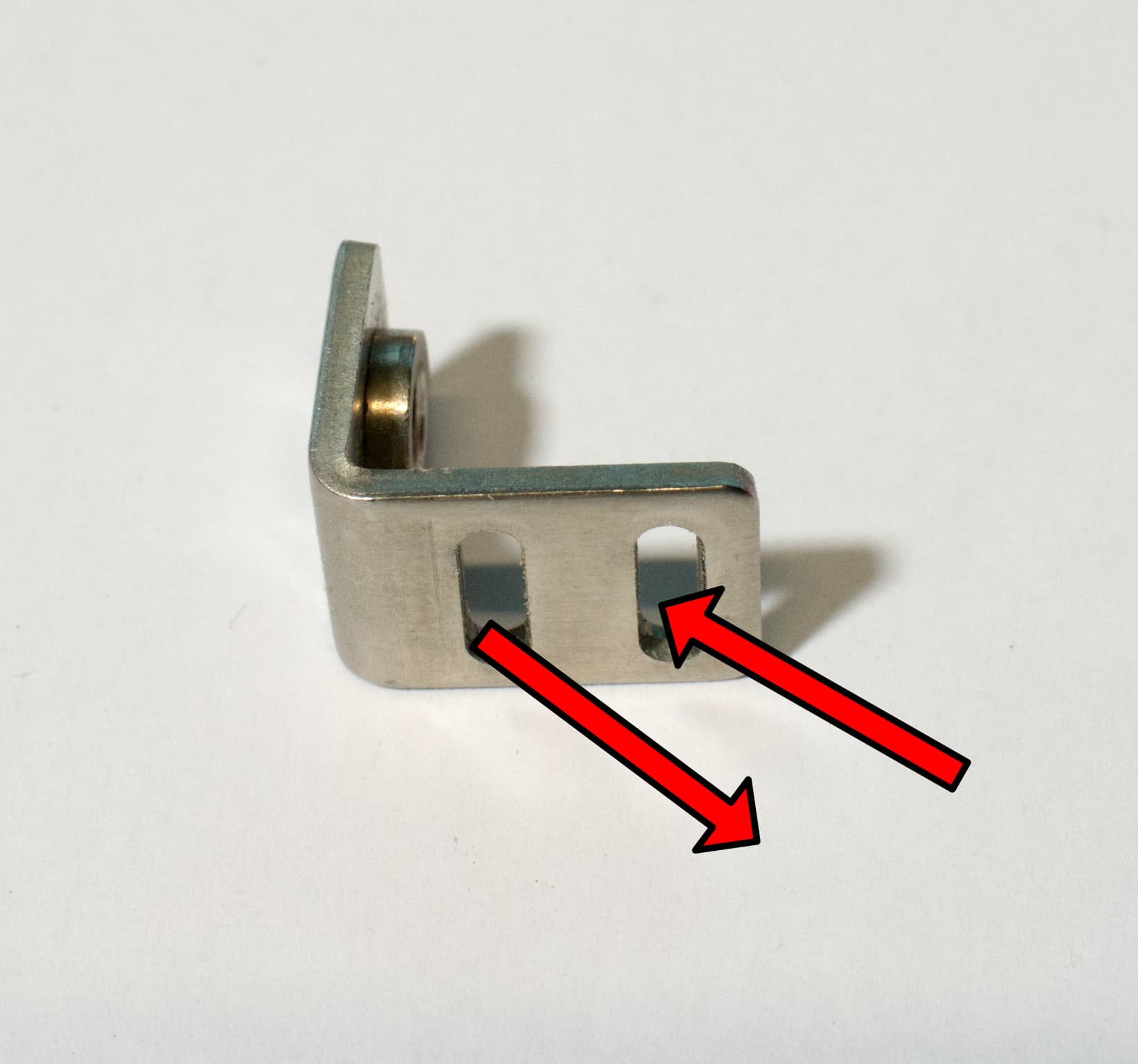
The belt path was not straightened but the pull was through 90 degrees. The image shows the clip where it was originally fixed.
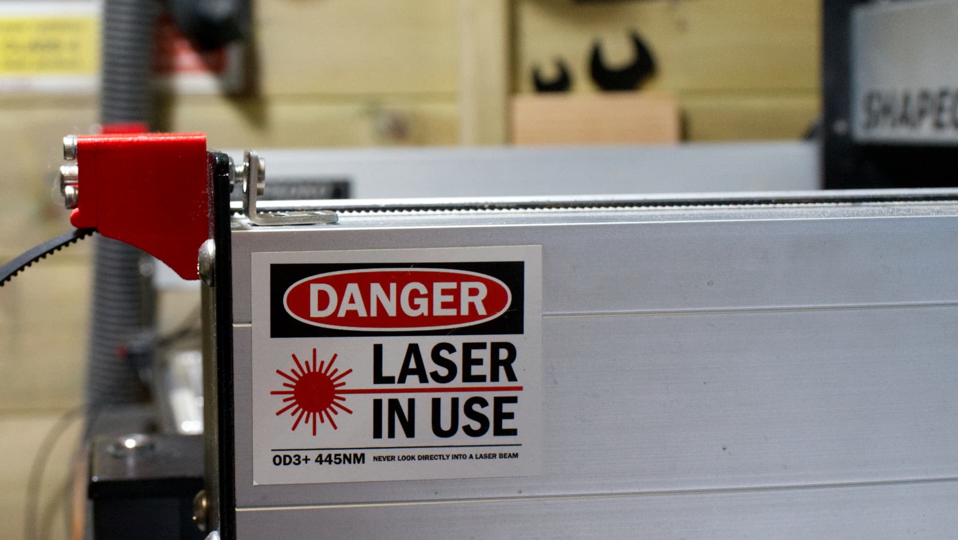
The clip was offered up to a screw hole under tension and the screw inserted into the frame work of the machine. It was difficult to maintain tension and screw the screw into the hole. The clip also impinged on the travel of the V wheels and they needed replacing because of abrasion damage to the V wheels. The solution was somehow to turn the clip away from the path of the V wheel so that it did not get chewed up at the extremities of carriage movement.
I hated the job of belt tensioning with a passion. I discovered a belt tensioning system that made more mechanical sense to me and it maintained a straight belt path. It was designed by @NeilFerreri and was published on Thingiverse. The link to Neil’s work is here:
I had some components 3D printed and carried out some surgery on my SO3. I now can tune each belt accurately in seconds rather than the extended times of 30 ~ 45 minutes that I had expended previous to this modification. I also now had an accurate method of tensioning the belts to a known tension value. The short video clip displays the method used to accurately tension the belts. All of the belts used in this demonstration are Gates GT2 specification.
Any and all comments welcome.
EDIT: Grammar and spelling and adding link to Thingiverse for Neil’s work.