GSender Keeps putting the model into the negative quadrants. Basically open GCode from VCarve Pro, the model ends up in the negative Y quadrants, spaced evenly between the negative and positive X axis.
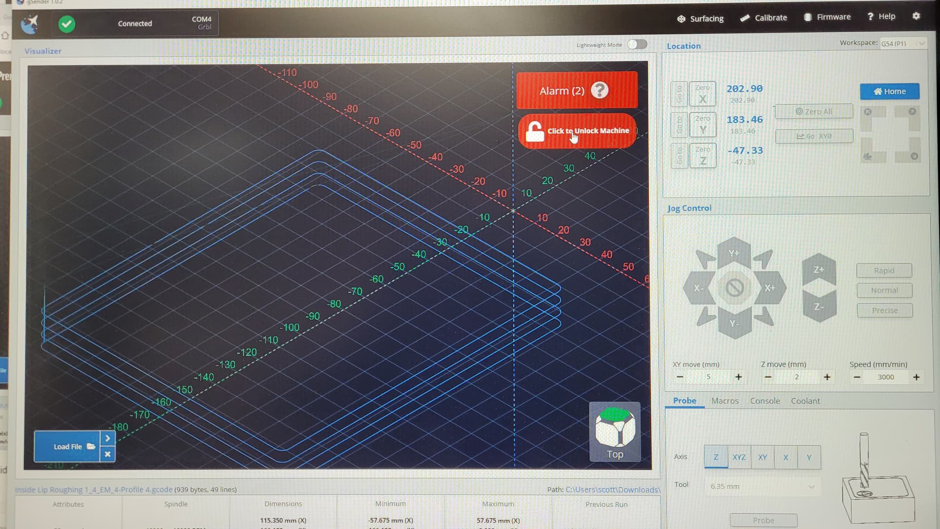
I home the machine with the inductive sensor in the front left corner as 0,0. I place my wood piece, zero X, Y and Z with touch plate and import the model. The model ends up in negative Y space on GSender and will not allow the machine to run by giving an Alarm (2) code.
To top it off, the Alarm(2) code will not Unlock when I mouse click the Unlock Machine button. I have to shut GSender down and start all over to clear the Alarm(2).
I added limit switches last week, and I am now getting soft limit errors in places where they shouldn’t occur; likewise, the alarms at that point that cannot be cleared without relaunching gSender.
Got hard limit error once in the middle of the workspace, but soft limit a number of times. If I can find a reproducible pattern I will forward it. I was using my laser when the hard error occurred, executing gCode from Lightburn. I changed Lightburn to use absolute coordinates, rather than relative after the hard error, and that didn’t recur (yet). When the soft errors occurred, I recorded the text of line in the console so I could find where in the file to restart. Relaunch gSender, homed, and used the start at line option to continue. BTW gSender did not turn on the laser at that point: I had to insert a M4 command at the line to tell it to turn on.
I ended up turning off hard and soft limits. Maybe someday, when Scienci figures out what’s causing them, I’ll turn them back on. @saskia , if you recreate a soft limit error check to see if the X, Y or Z coordinates really are out of bounds. The soft limits are based on the programing in the controller keeping track of X, Y and Z positions and setting an alarm if any of them exceed set values, so it would seem to me the soft limit errors would be a controller programming problem. The hard limit errors could be noise on one, or more, of the limit lines. Or programming.
Just to clarify, limits (both hard and soft) are 100% handled by the GRBL firmware. All gSender does is report alarms from the arduino itself.
@OP - Neil’s suggestion of looking at your postprocessor setup is a good one. gSender just displays the coordinates of the lines “as-is” within the file. You could look at exporting it with the XY datum point in the bottom left if you want your material setup in the bottom-left of your machine.
That’s fine, but why doesn’t GSender clear the Alarm(2) error when the soft button is clicked on? Having to shutdown GSender and restart every time is a pain.
@KGN , thanks for the clarification. GRBL FW running on the LM controller isn’t developed by Scienci, but I still stand by my initial thought that the Soft Limit errors are most likely a FW issue and the Hard Limit errors could be caused by electrical noise being interpreted by the controller as a limit triggering. Of course, the issue could be with how the FW handles the noisy input. I’m assuming that electrical noise filtering is the reason that Scienci provided the caps with the sensor kit.
Status: I turned off Soft Limits and restarted GSender.
I zeroed the machine and then I imported the GCode file again, and it still displays as comming up in the negative Y quadrants. With the Soft Limits Disabled, the Alarm(2) did not come up, so thanks for that advice, at least I do not have to restart the machine for the unclearable Alarm(2) condition.
However, now I get Alarm(1) conditions.
In order to even have a chance to run the model, I have to move the mill towards the middle of the waste board, Zero All for the coordinates and then when I just try to outline the model and Alarm(1)comes up. However I can clear Alarm(1) and then hit Outline again and it outlines the model and ends with Alarm(1) again.
I have a short 3-min video of the activity that I would like to try to post for this but I have no idea how. I will attach one of the GCode files here, but I do not see anything in the file that has negative movements in the GCode file. So, is there any setting in VCarve Pro that I somehow messed up that causes the model shown in GSender to mirror on the X-Axis so I come up in Negative-Y space coordinates?
I don’t think I got any soft limit errors. I got one hard limit error in the middle of a job and turned off both limits just to be safe. I guess I’m not too concerned about the using the limits. Having them on would also prevent me from running Y1 and Y2 back against the rear legs to make sure they are in alignment.
Most of the problems stem from my using Fusion360 to draft a solid model of my frame and then translating it into an STL file and then importing that into VCarve Pro. Essentially, the solid model and subsequent STL file follows the FUSION360 coordinate plane selection and the orientation of the object on that plane. Since I default my bottom layer plane of reference to the XY plane in Fusion 360, this is not the same XY plane as Vcarve uses. Subsequently, when I imported the STL file, it always came up on edge rather than flat to the XY plane of VCarve. Also, you have to watch out for the rotational basis in Fusion360 relative to that of VCarve. I was using the VCarve Solid model import feature and then using the VCarve Orientation function to place the model properly on its back side and then centering it on the wood workpiece. That really screwed up the milling position that VCarve finally calculated for the milling of the pockets and profiles. Hence it came up in GSender in the negative workspace areas and would not mill Alarm(1) and Alarm(2)).
Next problem was all mine. I was trying to zero the XY axes only and did not understand how to position the mill bit prior to this operation. I was used to doing an XYZ zero and this is the setup I tried for zeroing just the XY axes. Turns out, I was using XYZ zeroing start position, where you center the mill over the circle on the zeroing jig prior to starting the process, when in zeroing XY only, you have to position the mill end to the left of the work piece and below the bottom of the workpiece (assuming you zero at the bottom left corner); think of it as being moved diagonally outside of the workpiece from the original zeroing corner.
Now, realistically, I did not have to do a Zero XY at all. The zeroing process zeros to the center of the Mill Bit, so doing a tool change to swap to a smaller diameter mill bit does not affect its positioning for the finish milling.
I am sure this was obvious to all of you, but it has been a learning process for me.
So, all solved, but I really think not being able to clear the Alarm(2) condition in the original post is a true bug. or is that “feature”
Thanks all, we can close this discussion chain now.