Irregular depths on wastebaord

Hello there,

I got my Altmill 4x4 a couple of months ago and there’s one issue that I have trouble with. I am cutting melamine using a mdf wasteboard (milled on 2 sides) over a vacuum plenum. The wasteboard is bolted to the plenum and surfaced.

When I make my cuts, I end up with marks in the wasteboard about 3mm of depth on the sides and .4mm in the center of the gantry.

I use the ScienciLabs spindle with a .25mm compression bit at 70IPM and 16000rpm which gives me really nice cuts and no bit burning/breaking.

Any troubleshooting tips or solution for this would be greatly appreciated.

Is there a typo in your post ? 3 mm depth at center and 0.4 mm depth on the sides? A difference of 2.6 mm?

What does you vacuum plenum look like ? Is it just an empty space or is there support over the entire area? If it is just an empty void then it is likely that your wasteboard is bowed in when you pull a vacuum.

@Fab Welcome to the group.

Your compression bit is .25mm in diameter? Interesting. I can find end mills that small, but no compression bits. They must break if you look at them crossly.

If you are cutting into your spoilboard to a depth of 3mm in some spots and only .4mm in others, that would indicate that you have not surfaced your spoilboard and it is not parallel to your X and Y axes. I realize that you have said that your spoilboard is milled on both sides, but clearly something is off there.

edit. I see that @Jens and I were typing at the same time. :grinning_face:

Question: What CAD/CAM software are you using and where are you setting Z0 in it and in gSender?

Didn’t even catch the bit size …. I read 1/4”

@Jens I must admit that I checked to see if such end mills exist and they do. Until we hear back from the OP, I can only assume that he is cutting some very fine details into the melamine. :grinning_face:

Or, there are some misprints??? The bit size is in MM, the depth of cuts into the spoilboard is in MM, but the feedrate is in IPM, so I may well be reading this whole thing wrong.

Please let us know @Fab

I am surprised that there would be a compression endmill that is 0.25 mm. Regular endmill that size sure but compression style?

1 Like

Is there a typo in your post ? 3 mm depth at center and 0.4 mm depth on the sides? A difference of 2.6 mm?

No typo. 2.6mm difference between center and sides.

What does you vacuum plenum look like ?

My plenum is a 4 zones with 1 inch grid 1/4in deep with seal around each zone. It’s driven by a Hurricane pump with constant +/-10in vacuum pressure and the wasteboard is screwed to the plenum. I can move the whole machine by pushing on the melamine board when it’s on and it’s worth noting that cut pieces are staying in their place so I doubt the vacuum is the culprit but anything is possible.

Your compression bit is .25mm in diameter?

My bad. It’s 1/4in.

Question: What CAD/CAM software are you using and where are you setting Z0 in it and in gSender?

Fusion 360 for cad and cam and I tried setting the Z0 with the touch plate and also on the manually on the middle of the board. there’s a slight difference when I set it on the middle but it’s less than .5mm.

Or, there are some misprints??? The bit size is in MM, the depth of cuts into the spoilboard is in MM, but the feedrate is in IPM, so I may well be reading this whole thing wrong.

Other than the bit size, everything is ok.

My next step is to take a micrometer with a magnetic base and drive it around the wasteboard to see if anything isn’t true.

Another thought … I would test to make sure that, once a vacuum is applied to hold down the work piece, there is no gap between work piece and table. My thinking here is that in the event that the sealing strips do not compress enough, your work piece will only sit on the seal and not be supported by the table. This would allow the work piece to dip in the middle giving you a deeper cut in the side areas compared to the middle areas.

A simple test would be to put a strip of paper just past the outside of the seal strip but still underneath your work piece. Apply a vacuum and make sure that the paper is held tight and can’t be slid out. If you can easily pull out the strip of paper than your workpiece is ‘floating’ on top of the seal strips

Hey all. Sorry about the very late reply but I was busy with other things so it took me 2 weeks before being able to run some tests again.

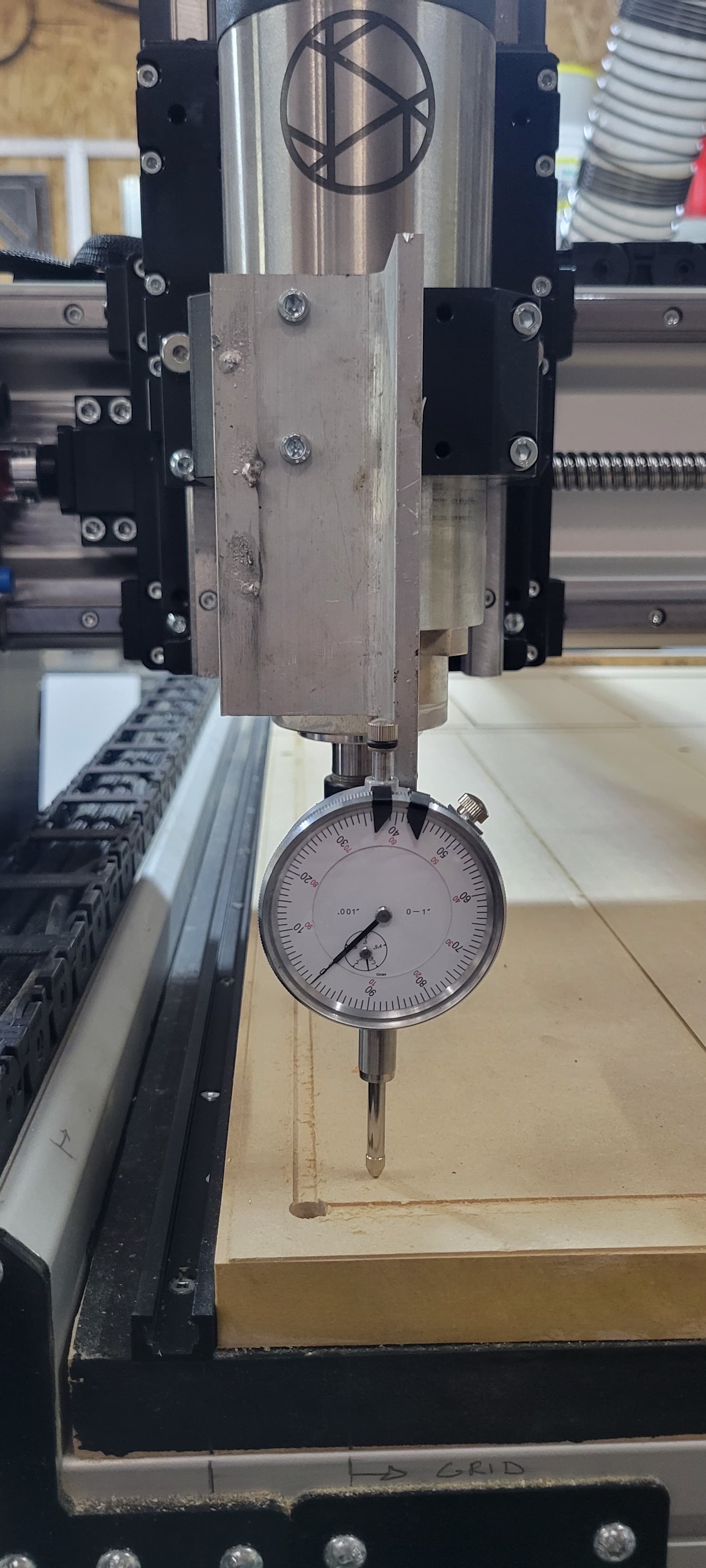
I did a lot of testing starting by attaching a dial indicator to the spindle mount to check the flatness of the spoilboard.

I took measurements of points in a grid pattern and came up with a delta 0.014” from the lowest to the highest which is fairly acceptable and far from the errors I noticed in the cuts.

The measurements near the middle of the table were the highest so I decided to improve my plenum design. Even though it wasn’t the decisive factor, I decided to improve it while I was making changes. I initially designed it to mount a t-track to the middle section but it forced me to use a 2 part spoilboard which kind of reduce the vacuum. force in that area. This could be problematic when machining smaller parts over the middle section.

Next, I turned to Chat GPT since I was clueless about the next troubleshooting steps. It was pretty instructive in understanding the lead ins and lead out, finishing passes and more but it couldn’t find the fix.

One day, friend came by and, as I was explaining him how the machine works, I noticed a jerk in the Z-Axis movement. It was very quick and I couldn’t repeat it but I inspected the Z-Axis assembly and noticed that the motor coupler was holding the red PU bushing by the end of its “fingers”. Then, a closer inspection revealed that the black locking collar below the coupler was also loose and it was resting against the bottom of the coupler.

This collar actually supports the weight of the spindle and it has 3 locking screws which makes it very strong. On my machine, it was loose so all the weight of the spindle was pulling on the coupler which only has one screw. So it ended up dropping almost out of it’s “fingers”. When cutting, the spindle would catch the slack and cut higher but gradually “eat” down in the material while moving until it was at the set Z-value, creating slopes and irregularities in my cuts.

I looked at the assembly manual and couldn’t find instructions to check the tightness of the collar and coupler (it comes pre-assembled) but I would highly recommend that this is checked at the time of assembly.

Anyway, I learned a lot while troubleshooting this and hopefully this post can help others at some point.

Thanks to all of you who replied! This was appreciated.