Hello folks, I am having an issue with my Longmill cutting everything but square. Over an eight inch of travel, it is off by just over a 16th of an inch. So everything I mill is just a bit cattywhompas.
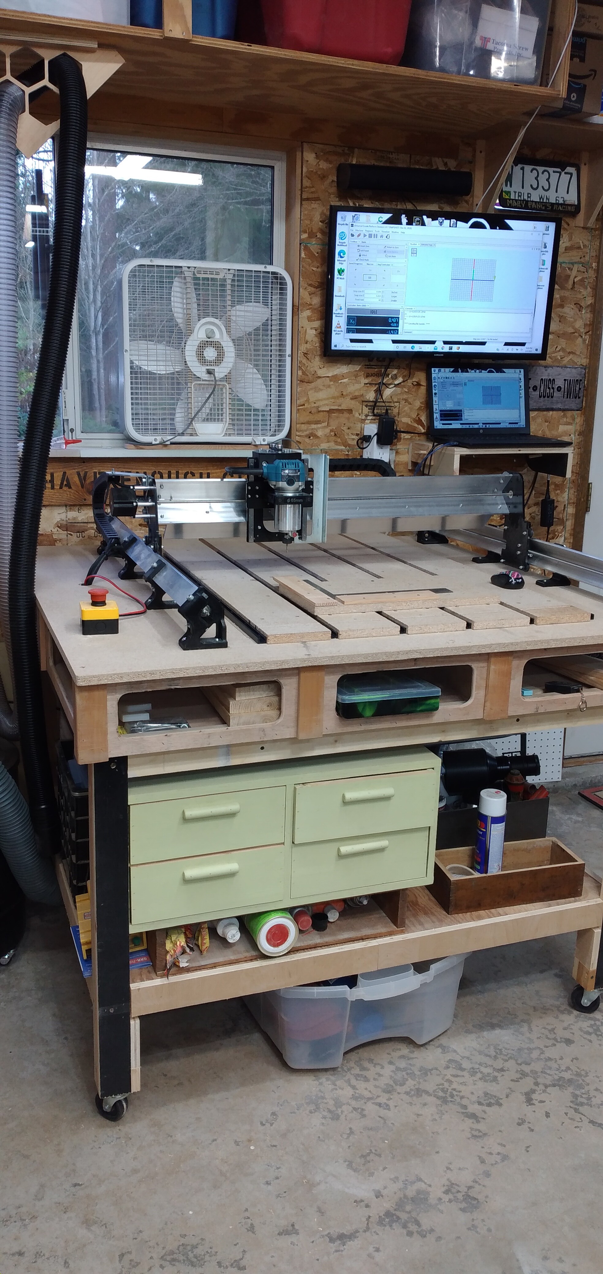
I have screwed down a second piece of spoil board and secured 2 strips of wood at close to right angles as I could. Then manually cut the edges on X and Y axis and it shows how much it is off.
I went back thru the setup instructions a few times but if I’m missing something, I’ve missed it a hundred times…
I’m shooting up a flare here and would appreciate any help.
@W.g Which axis is out, Wally, X or Y? Or can you tell? Since you’ve gone over the instructions many times, I’m likely about to suggest stuff you already know. These are in no particular order.
Check the delrin wheels to ensure that none are too tight.
Check the anti-backlash nuts to ensure that you have no movement in X or Y and that they are not overtightened
Check the electrical connections to all the motors
Make sure that the couplers between the motors and the lead screws are tight.
If the issue is with the Y axis, switch the leads on the controller to see if the problem changes sides. If it does, at least you will have narrowed the problem down to the motor or the motor controller on the bad side.
Again, the problem is in Y, run the X gantry all the way back until you hit the stops, then run it all the way to the front.
Went down the list of things you advised. Used 3 4 5 like NUTZ and it is about 3/32" short on the long side measurement. I actually used the same orientation as the video only with 15" Y 20" X .
I’m not sure how to make the adjustment then make it “permanent” or repeatable.
@W.g Peter’s video is excellent, I found, but we cannot adjust the Mill the way he adjusted his CNC. You have two choices, as I see it. Others may well have others. You can remove all the screws from the Y gantry, tap it back, clamp it and make your test again. When you have it spot on, replace the screws. The issue with that is that, it is likely that you won’t move the Y gantry enough to be able to drill new holes for the hold downs. That was the case for mine, anyway. The other solution is something of a “cheat”, and is the one that I chose for my Mill. My Mill was out of square by about 1/16". I put a 1/6" shim at the front of the Y gantry, brought the Mill all the way to the front until the X gantry hit the stops. Then I ran Peter’s test again. It took me 3 or 4 times to get the thickness of the shim spot on. If you choose to fix yours this way, you need to remember that you cannot choose to “square” things up by running the Mill to the back. (I guess that you put a shim of equal thickness at the back corner opposite the one in the front corner. I didn’t bother.) You will note in Peter’s video that, when he had his dialed in, he ran his X gantry close to the front limits, then moved is limit stops to touch the gantry. That’s basically what I did with the shim. So far, I’ve tested mine a few times in the months since I did this, and it has stayed spot on.
Thank you, I am going to try adjusting the right side Y gantry. It should be possible to fill in the existing screw holes so I can resecure after the adjustment is made. The clamping will be a challenge though.
Its reassuring to know that other CNC owners have the same issue, it makes me feel less dorkish!
I owe you one Grant, thanks again. I’ll let you know how it turns out.
@W.g You’re very likely right, Wally. Mine did not need to move enough to clear the holes, and I didn’t want to unscrew the other side to move everything. Clamping can be a problem. It doesn’t take much. FWIW, I ran a board from the front of the table to the back, through the front and back feet, and clamped the board to the table with F clamps.
Dead reckoning and an answered prayer helped my hit it on the first try!! I marked where the front foot was originally and moved it just a bit further than 3/32" forward. Took a leap of faith, screwed it back down, set the spacing on the gantrys and it worked great…
Take a bow my friend, this victory is mostly yours.
Going to set up the touch plate today. I run the machine in inches, if I set the plate up (like the demo shows) in metric units will that work? Or will I need to convert all the mms to inches?
@W.g Wally: All my projects are in inches, but I run the probe module in mm. Works fine. The big thing to keep in mind, if you are using the plate for X and Y, is to get a good measurement in mm for whatever bit you are using when you run the module. I set X0Y0 in the centre of my piece for most projects, and use the plate only for Z. However, I do use the plate for X and Y from time to time. I use a piece of drill rod that is spot-on 6 mm for the measurement. Then, change to whatever bit I am going to use.