I am reaching out for assistance with my LongMill Mark 2. I have been experiencing difficulty achieving flat bottoms in the pockets I create. I have tried using upcut, compression, and downcut bits, but none have yielded consistent results in producing a flat pocket. I have also attempted raster toolpaths, as well as multiple passes, but the issue persists. When I rerun the program, the humps appear in the same locations.
Although downcut bits seem to improve the situation slightly, they still do not provide the flatness I am expecting. Even when using different toolpaths with clearing bits, I continue to encounter similar anomalies. I am unsure whether this issue lies with VCarve or the LongMill itself. However, since the toolpath appears flat in the program generator, I believe VCarve may not be the cause. Maybe some flex in the machine or z axis worn out, only 2ish years old.
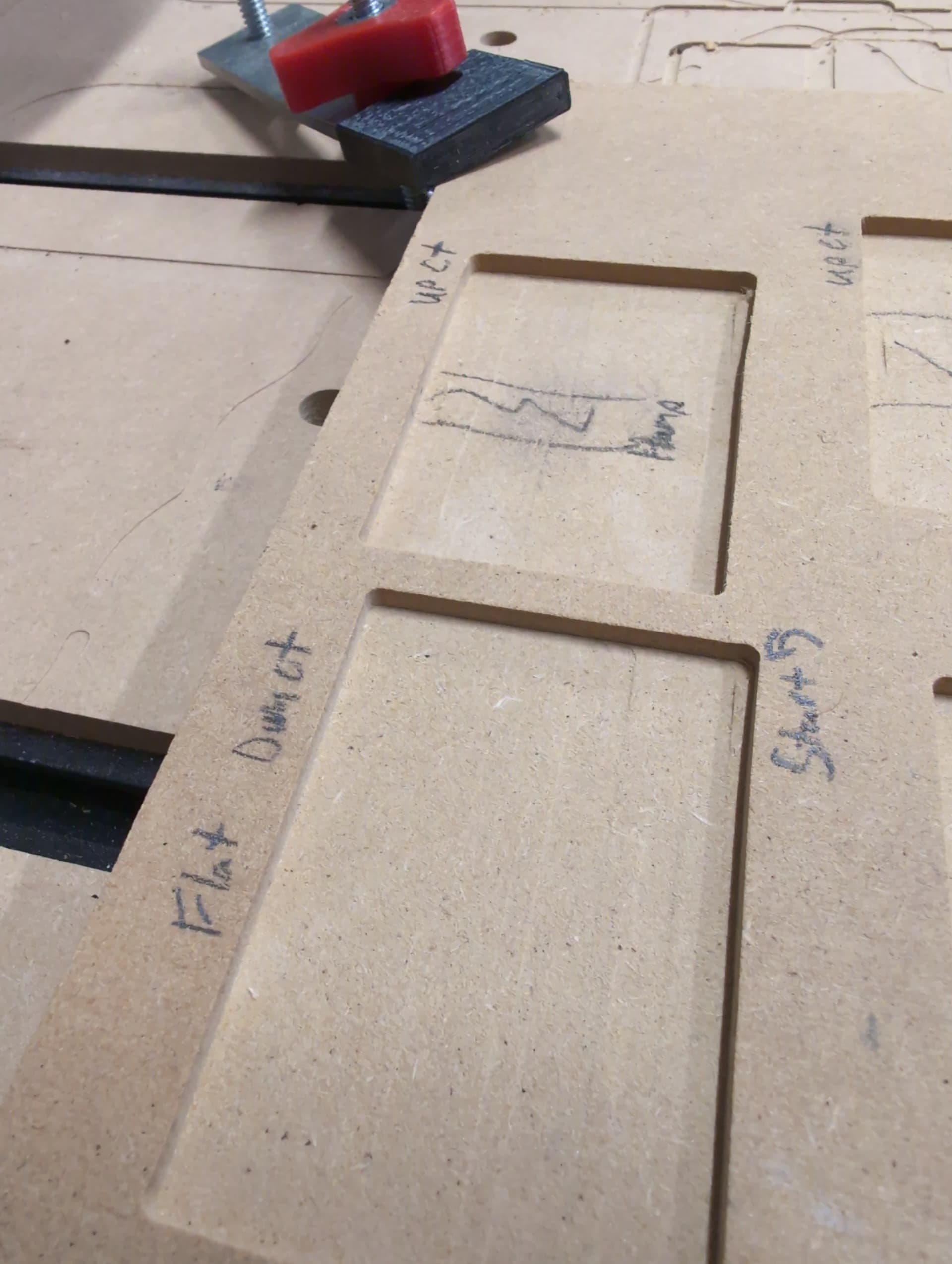
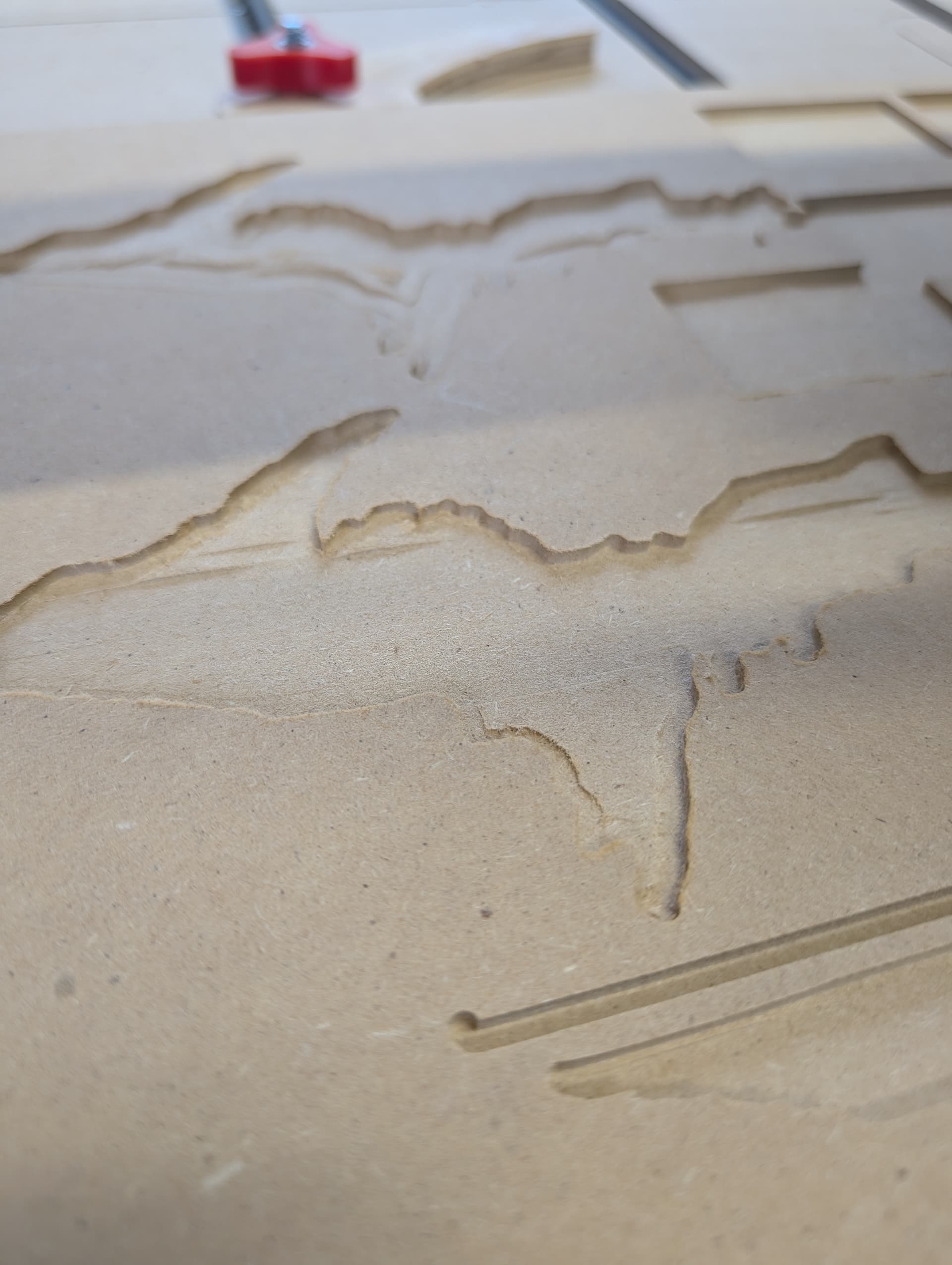
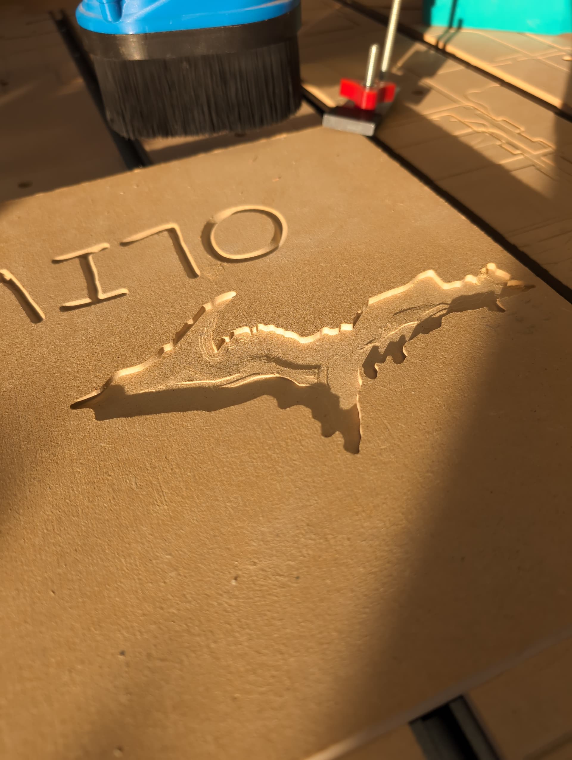
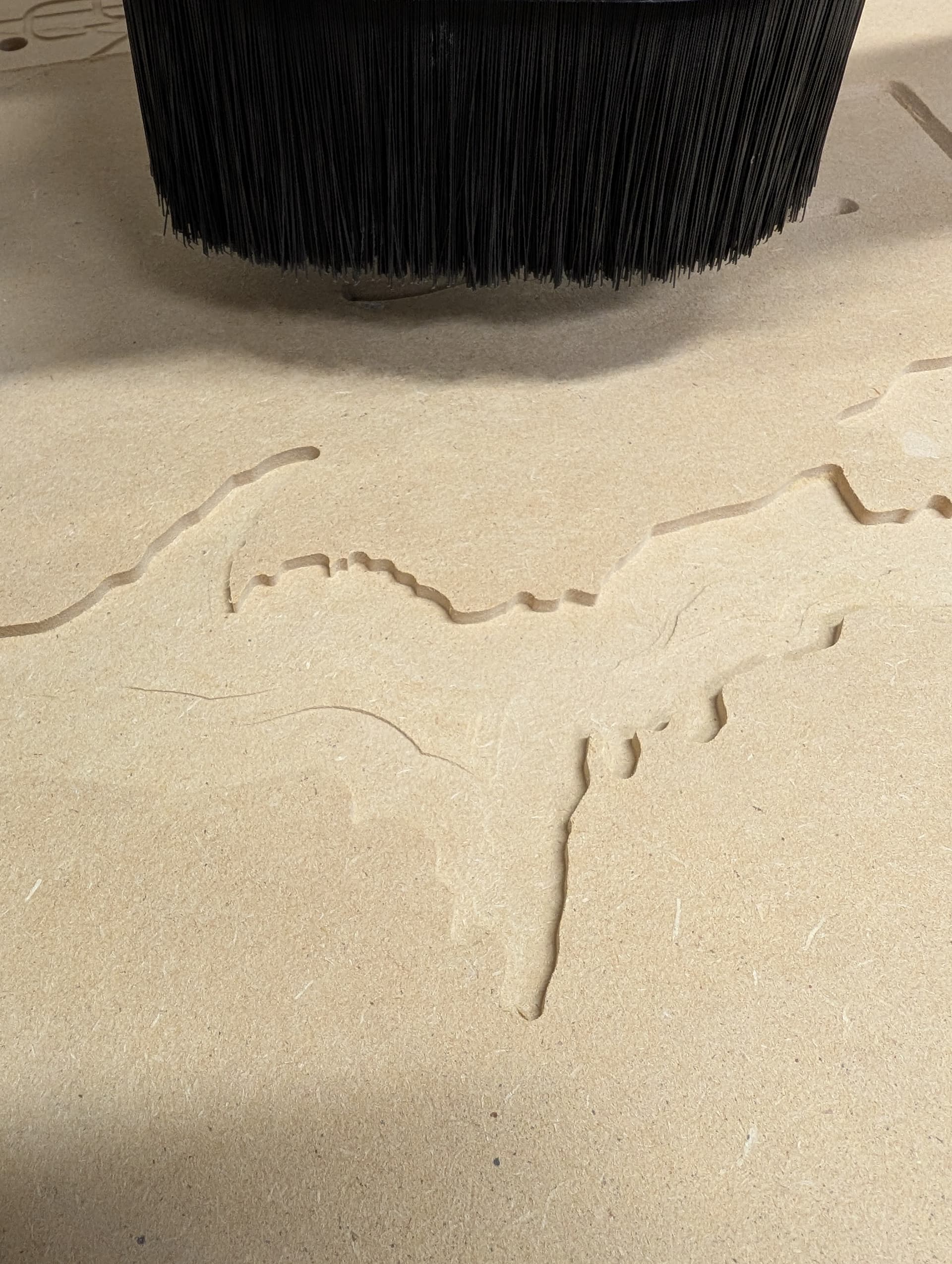
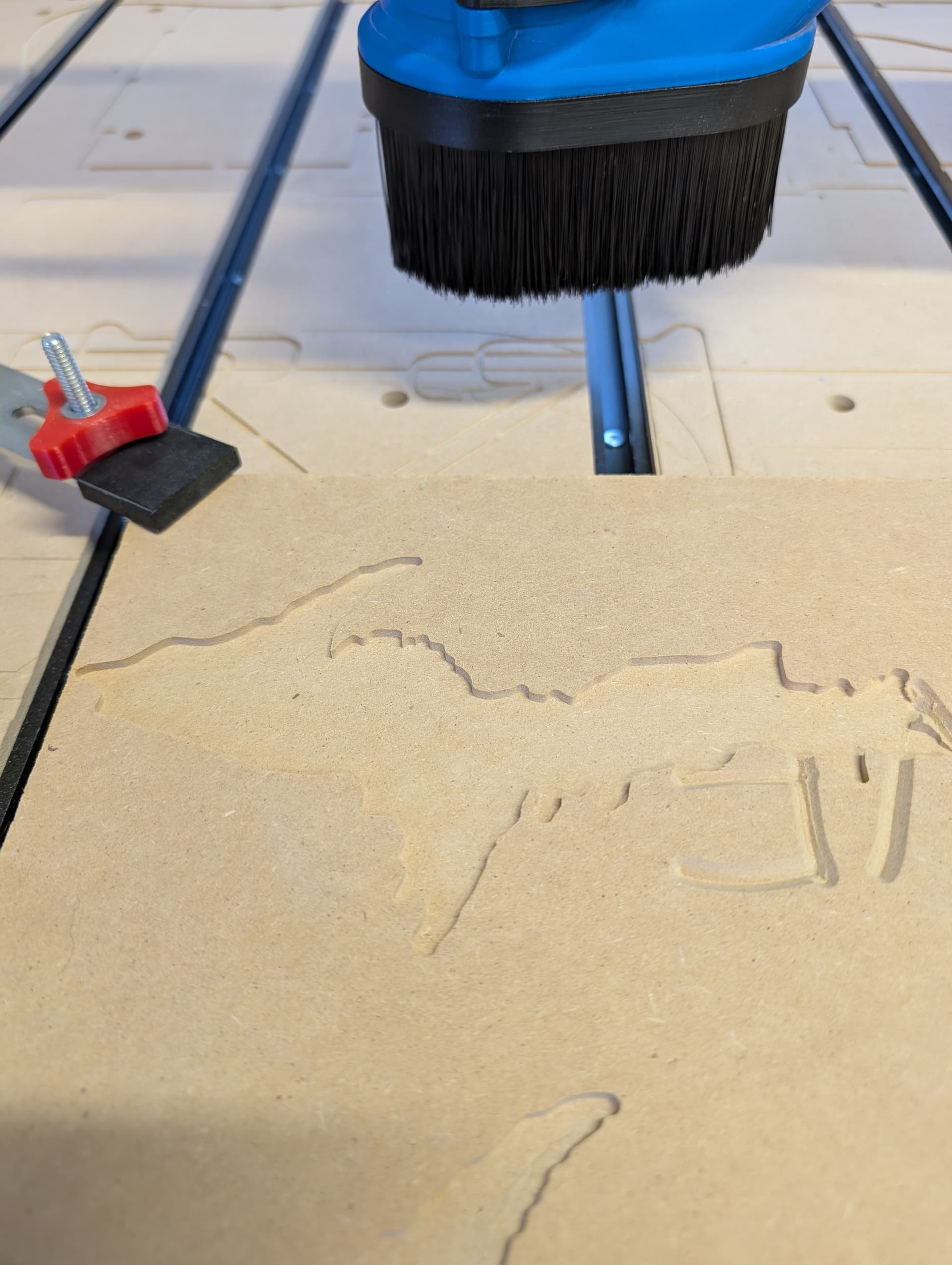
Pictures below show the severity of the problem.
I would appreciate any guidance or suggestions to help resolve this issue.
Ughhhh - that is ugly alright. looking at the top right of the picture, there appear to be some pockets that are perfectly flat - does this problem only occur on some pockets and not others? If so, is there a pattern to this that might give a clue? Are rectangular pockets fine but irregular pockets are messed up?
I used a downcut bit with raster settings, but I also tried the same process with a compression and an upcut bit. In all cases, a smooth ramp or hump appears in the middle, about 0.029" above the bottom. This issue is more noticeable with irregular shapes. I planned to add more pictures, but I couldn’t for some reason.
Something is definitely loose.
By the way that the angle of the cut is changing and that you mention the downcut endmill slightly improves things, it seems like the X gantry is swaying around,
I would start by checking that the X gantry V-wheels are tight and properly aligned.
I suspect something else is also loose though, it could be in the machine and/or clamping.
I’ll check the x Gantry for anything loose. I highly doubt it’s the wood moving. Seems weird it’s so consistent but I’m willing to try anything. Its done it a bunch more different times on different projects. Would the new self adjusting anti backlash nuts cause this issue?
Also would it not be a problem with the z axis sense it’s a up and down anomaly not side to side or back and forth?
Plus I can try to send the g code to see if anyone else has this same issue, if anyone is willing to try it, then that would help narrow the possibility of it being a program error?
Might be a long shot, but is that cam clamp pushing the board up in the middle, causing it not to sit flat? Just guessing as I have had that with a couple of clamps that work similar.
I went through the whole machine checked everything, made sure there were no loose bolts, lubed where needed and I found a few loose v wheels. Machine is all tight. I just ran a test w/ clamps holding downward pressure and it still didn’t fix anything, maybe a little bit better.
I did not run your files but did have a look at them. The up -pocket_1-Pocket 1 shows consistent Z moves and once it goes down to -3.175 it stays there until the next retract (to z5.08). Does not appear to be a gcode issue.
However, the other file shows significant Z moves over about ten lines of code (at several different locations) - all while moving in both X and Y. It looks like it is trying to carve some “features” at several locations. Running it on CAMotics it looks like your cutting a pocket in the shape of a lake with the contour of the lake bottom is what your seeing. Looking at the gcode, your getting what the code is telling it to do.
Suggest you create a vector around the pocket your trying to cut and then select that vector and pocket it alone and see what happens.
An X-gantry with one loose v-wheel will move the tool like in diagram A, but with two loose wheels it will also move the tool like in diagram B.
Deflection in the machine will usually only move the tool a small amount like in diagram A.
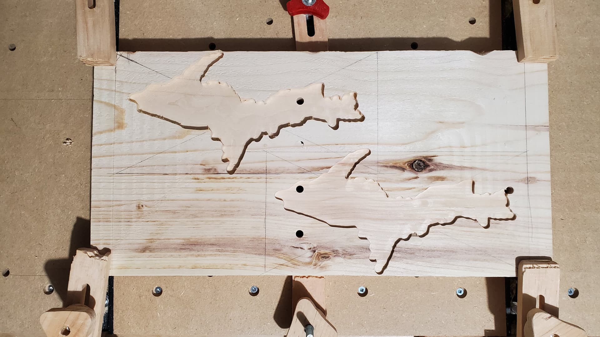
I wont run your g-code how you programed it to be ran, but I tried few test cuts.
First test was at the full 1/8" depth and full feed rate but with a 1/4" Upcut,
It didn’t turn out the greatest, there were a lot of tool marks from deflection, not nearly as bad as yours are though.
I went over it again at a depth of about 1/16" and that cleaned it up nice.
Second test was the raster toolpath, it was done with two 1/16" passes, at full feed rate, with a 1/4" Upcut, it came out okay.
Third test was with a 1/8" Upcut at 1/16" depth per pass and ran at 76% (43/57inch/min) feed rate.
I didn’t feel comfortable raising the feed rate any higher. It came out good.
I think most of your issues are now caused by deflection from your feeds and speeds not being setup properly.
Adjust the tool database with the following and turn off plunge moves, try again at the full 1/8" depth and see how it goes.
@cjm
Just ran another test, I made sure all parameters for the bit are exactly how you had it. It came out exactly like my last test. I usually run IDC’s tool database so I don’t have to worry about changing much when creating jobs.
I wonder if there’s a problem with g-sender’s firmware?
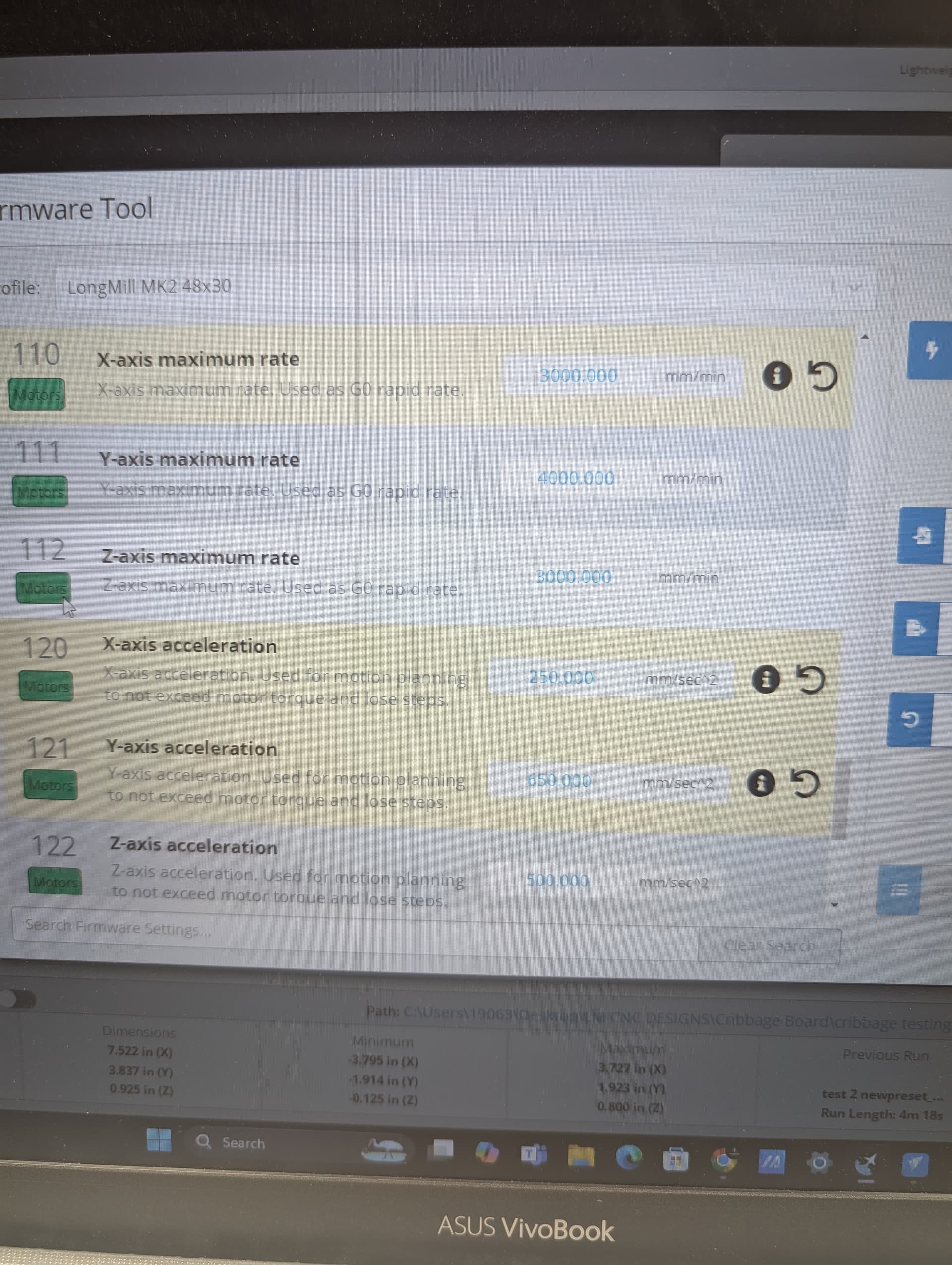
I changed a few x-axis acceleration and maximum rate due to having my x axis stepper motor stall out when moving rapid/fast moving during projects after I installed the new self adjusting backlash block. I never had it happen sense but maybe something in there is goofed up? ( I found these settings recommended on the Facebook group after finding other people having the same issue)
It’s also not a lake, it’s the outline of the Upper Peninsula of Michigan, but not the first time it’s been mistaken as a lake. So anyway it should make a nice flat pocket, yet I can’t seem to do that.
Sorry I mistook it for a lake! Hard to discern other wise. I do not know why your offset toolpath would have all the variations in Z depth. Can you share your design (Vectric) files?
Len
@Joel.S Unless it’s just the lighting in your images, I continue to see progress.
The machine doesn’t look to be losing position, so it’s not a software issue (or anti-backlash nut issue).
As long as your machine is tight, I’m sure the problem is deflection in the tool and Z-axis assembly.
I think you’ll have to experiment with a reduced feed rate and pass depth until it cuts properly, your project has an aggressive toolpath, Also starting with a 1/4" endmill and then finishing with a 1/8" endmill could be beneficial.
As you mentioned earlier something could be worn, flexing and causing the problem, but that shouldn’t be the case after only two years.
You can quickly check the deflection by dropping the Z-axis almost all the way and wiggling the end mill, stuff will move a little bit but it shouldn’t be much at all.
What collet do you have for the 1/8" endmills? If you don’t have one already, this style is the best to use.
Yes restore the firmware to defaults, I don’t think there’s a need to flash GRBL.
I’d check your feed rate next. If it’s moving too fast, the milling may be inconsistent.
However, when you rechecked the wheels and readjusted them, you said that it was better, and that tells me that something was out of alignment.
Before you do any further milling on the actual material, after slowing down your feed rate, I’d suggest to do a very simple straight line slot on a piece of MDF. Make it something like 500cm long and only the thickness of the mill itself. Then, using a precise depth measuring tool (I imagine you’ve got a dial or digital caliper) measure the depth at various points to see if it’s maintaining its depth consistently. If that checks out, then go ahead and do the same thing, only widen the slot to 5 times the width of the mill. If that checks out, then I’d be confident in recommending going ahead with a test of the actual shape of one of the pieces, using some scrap material.
Let us know how this checks out, as this is pretty unusual.
Marty from Kingston, ON
Got it figured out, sorta! It was the firmware setting making it act weird. Now it cuts flat like it should. Except now, when I do rapid movements, it stalls the x-axis motor out.
Has anyone else had this issue w/ the new self-adjusting blocks?
The x-axis one is the only one with this problem, all others don’t stall when rapid moving. I had this problem before and the different firmware settings fixed it but then created the problem this thread is about. Maybe smaller blocks have less tension on the lead screws and that’s why the big nut is the only one that does this?
What fast/rapid rates are you using in G-sender/ v-carve?
My v-carve was at 157in/min, which I never had an issue with until the new nut, so I slowed it down to 120in/min. Hopefully this helps. I didnt do anything in g-sender yet sense I don’t want to screw more things up.
Thanks for all the help again, soon I can be creating projects with confidence.
Glad to hear you’ve got that part fixed.
I don’t have experience with the spring loaded nuts, but the regular X-axis nut can cause the same problem if it’s not precisely aligned to the lead screw, and in the times I’ve had to do it so far, it seems that it takes mostly patience and luck.
I start with the X-gantry at the left of the rail, loosen the anti-backlash block bolts from the X-gantry enough so it has a little play and run the gantry down the rail and back, and then tighten the nut by turning each bolt a little at a time, trying not to move the nut, and then test it out, usually repeating several times until it’s properly aligned.
If the issue persists, the block could be too tight. I’ve also found the cause to be debris inside the nut itself(oiling the lead screw is not the greatest idea), build up on the rail, and even a faulty v-wheel with a flat spot.
I doubt to be your issue but my machine also has a slight defect so I can’t fully tighten both the X-gantry v-wheels and anti-backlash block bolts at the same time or it jams on each end of the rail. I keep my wheels slightly loose to overcome the issue.
I think the VCarve setting you’re referring to is for the time estimate which is 157in/min by default. The Rapid Rate G0 is set in the firmware under the $110,$111, and $112 maximum rate settings. I just use the default values.