Hello all,
Today is the first day in awhile I was able to get into the shop and continue on my journey in the CNC world. I originally purchased a Gcode file for my CNC based on an Infinityone CNC unit and have since abandoned that until I get much more proficient.
So I purchased a Gcode package from IDC Wood Craft for the 48x30 MK2 Spoil board. I am at step 4. After working through some issues as to why my unit will not return to the X/Y zero exactly. But that is for another day to resolve that and maybe a call to Sienci. So onto step 4 in the IDC instruction manual for making the Spoil board after cutting all the alignment holes in step 3 and then fighting with the loss of x/y zero and re-zeroing everything and moving forward ,to step 4. The gcode ran through all of it’s steps but did not cut all the way through after three passes for cutting out the spoil board. I am using a 3/4 inch MDF sheet purchased from a Cabinet/hardwood supplier of raw materials. The MDF is cabinet grade at 97 inches by 49 inches by 3/4 inches.
So after the first time of running the gcode through gsender and watching in wonder how clean and fast the cnc was making holes and cutting the board out. I moved everything back to zero and it seemed that the cnc went to the zero that was set in gsender for x/y/z. Then I noticed that the Z axis did not plunge all the way through the 3/4 inch material.
So I checked my bit ( Amana 46201 Solid Carbide Spiral Plunge 3/16 Dia x 3/4 x 1/4 Inch Shank Down-Cut #46201Specification : Direction; Down-Cut : Diameter 3/16" : Cutting Height 3/4 " : Shank 1/4" : Overall Length 2" : Flutes 2) To make sure it did not slip and go deeper into the collet. The bit was in the same place as I set it in the collect. 1/8" from the flutes into the collet. Might be my error there, but I dont think so. I am 1/8 inch from cutting through into the work bench subbase top. So I reran the gcode resetting the Z axis to the spoil board top with a piece of paper barely able to slide under the bit. Still no full cut through the spoil to be top.
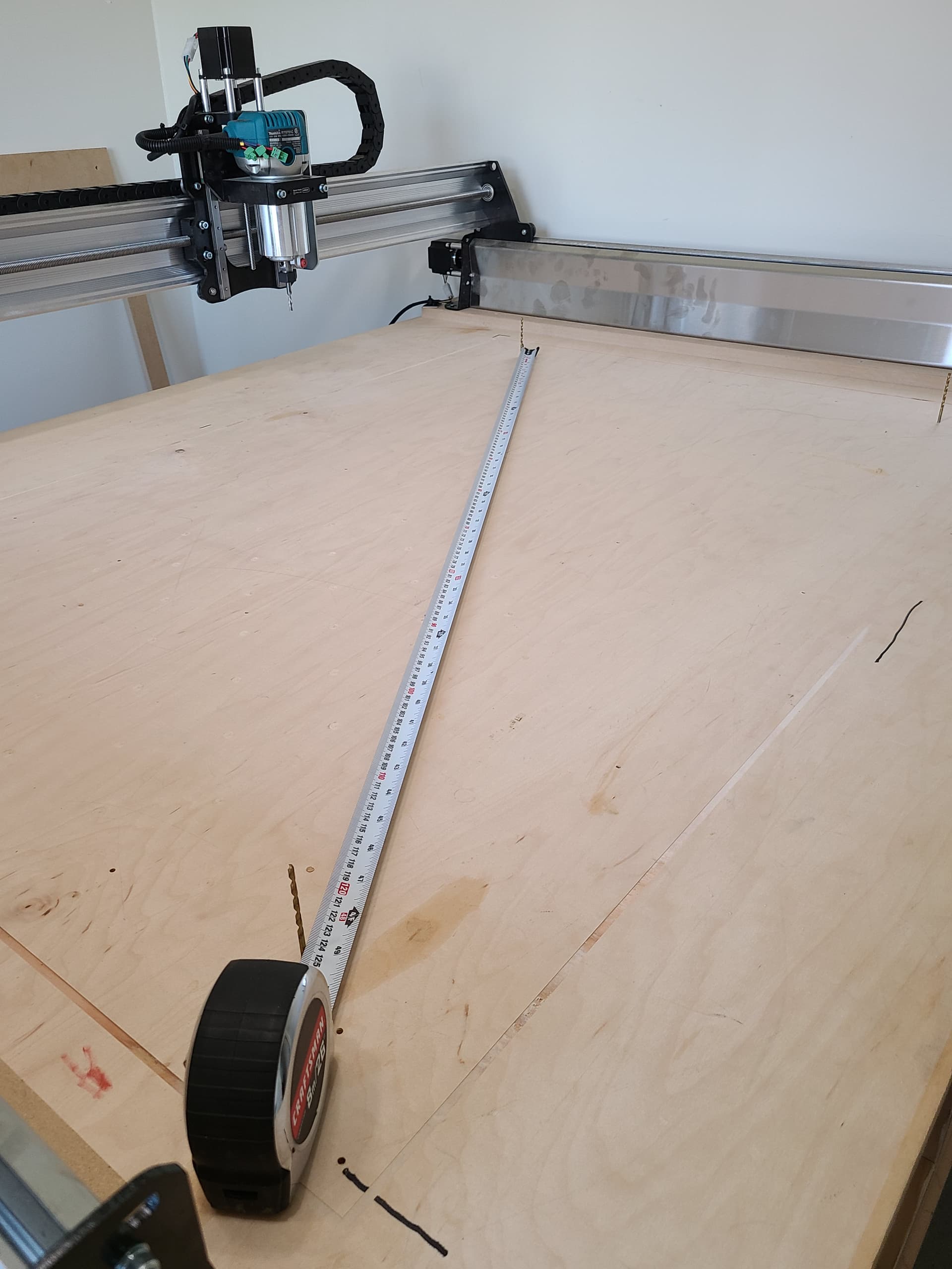
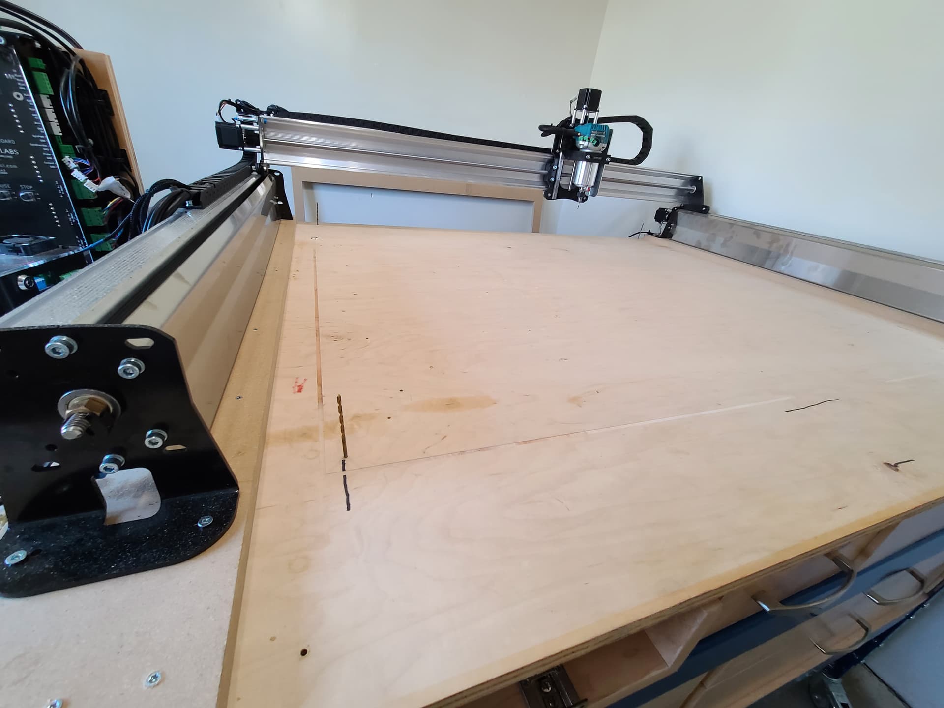
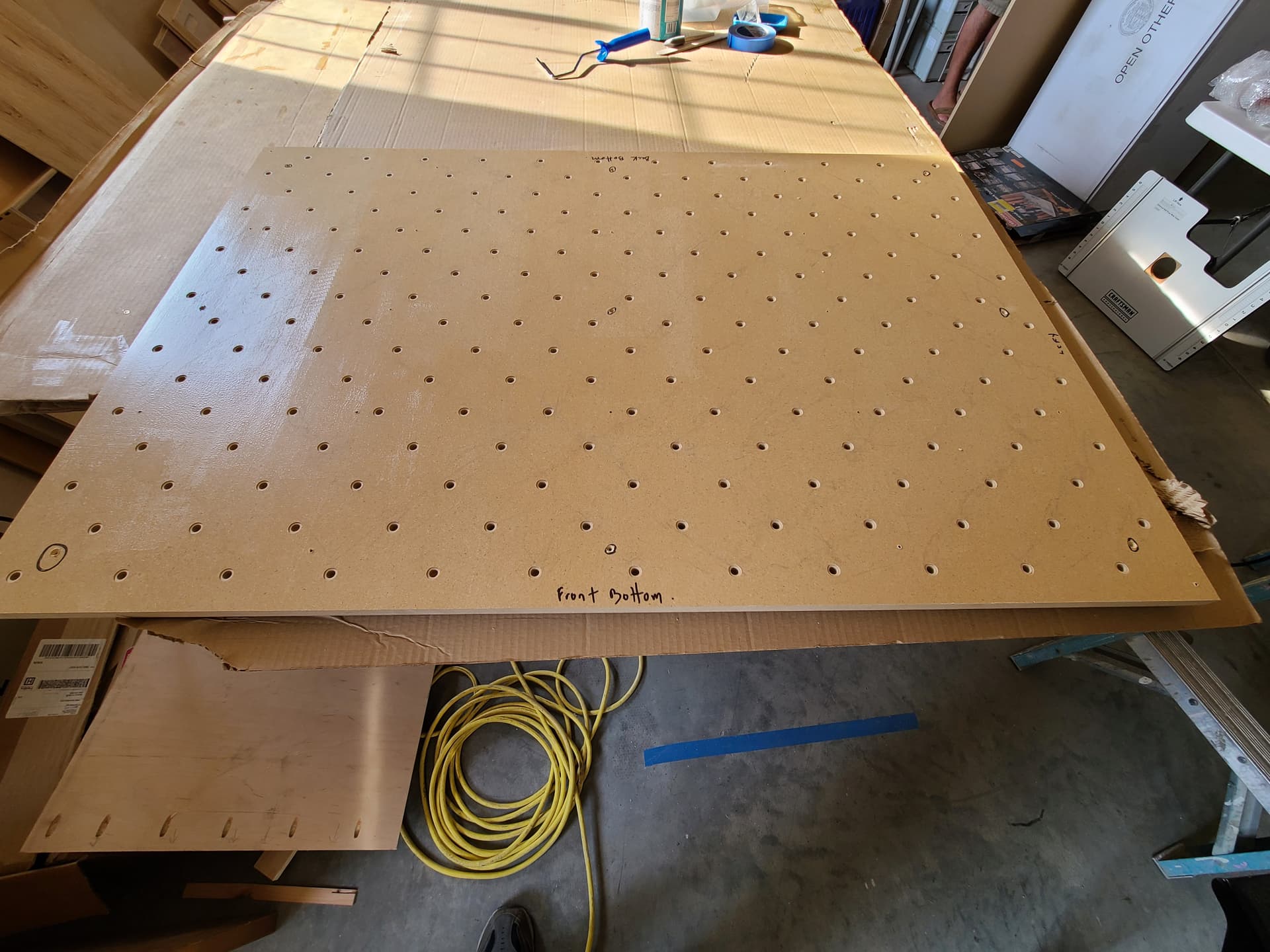
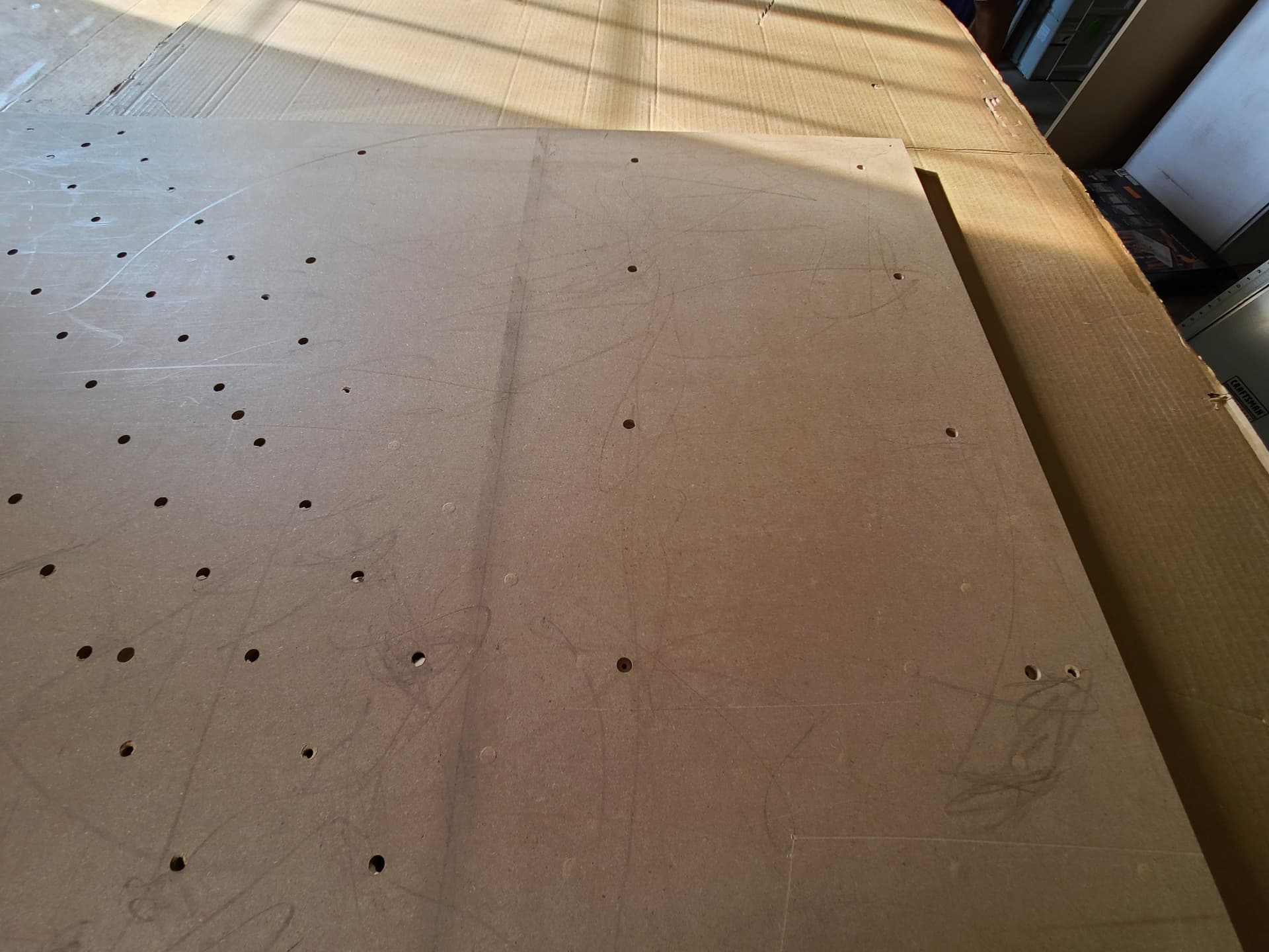
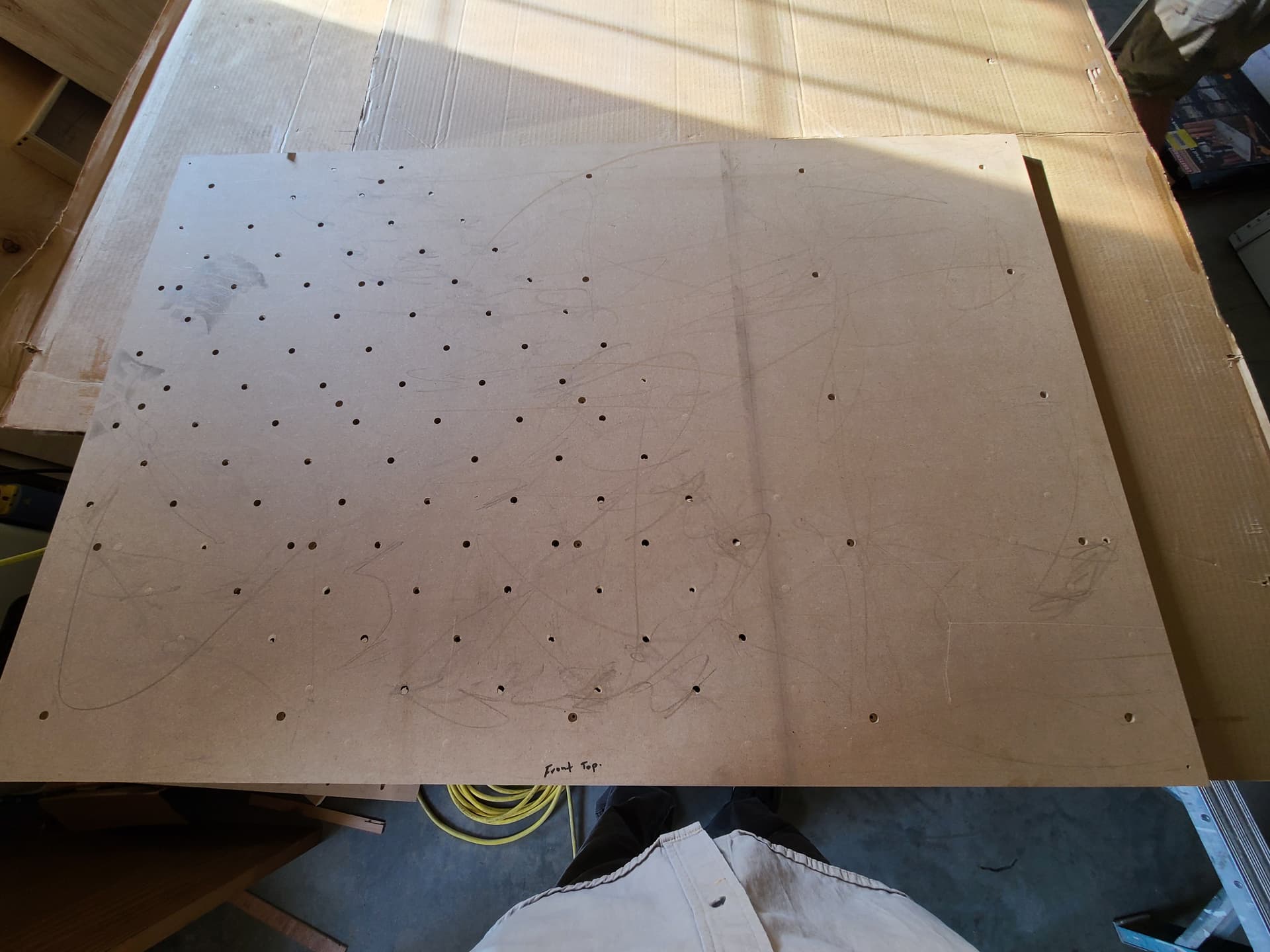
I took some pictures posted here
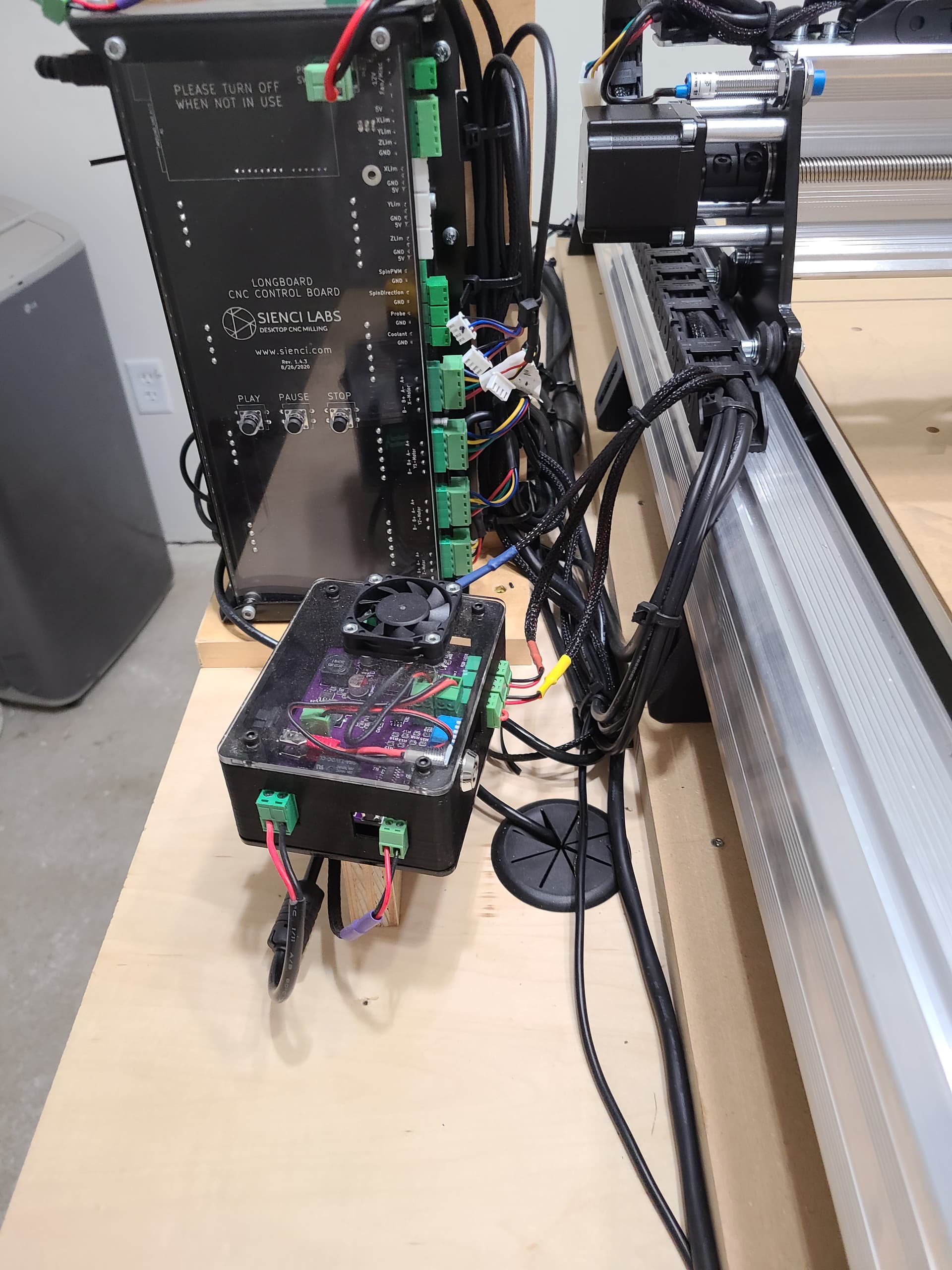
I have sensors and they are all disconnected and have not even been setup yet in gsender. I have included the gcode that I purchased from IDC to be used only for technical support as I did not create the code. 4 Mount Holes C-bore & Cutout 316dc.gcode (9.1 KB)
Since I do not know how to properly read the code and where to find the plunge data with in or if I am using the correct cutting length of 3/16 bit as the bit on IDC Woodcraft web site lists a 1 inch cutting flute length and I am using a 3/4 " cutting flute length.
I also want to mention that my CNC is mounted 3/4 inch higher than the subbase putting the IDC style spoil board even with the cnc bottom mounting legs. Pictures have reference to that and that I have sensors disconnected.
As far as I can tell I either have
the bit too deep into the collet .
There is a Plunge depth error ( I based this on opening the design file in Vetric and saw that the project depth was half inch) ( But the pdf manual and the video from IDC Woodcraft both reference a 3/4 " deep plunge after 3 passes. Longmill MK2 30x48 Spoilboad Design file DXF.dxf (1.6 MB)
I really want to get this cnc working. and the first steps for me is to get a spoil board to start learning how to use the CNC through trial and error. I say this because after assemble I had some issues with the cnc hanging up and it turned out that the machine oil I used to lube was a biodegradable oil and is degraded ns gummed up the works. After much forum searching and reading. I settled on a teflon based silicone spray lube and after tear down and removal today of the lead/ball screws of all axis and acetone cleaning and then lube re-install. Then break in run , then re-check for square, re-tune, loss of the x/y axis multiple times. Then the running through 3 of the IDC Woodcrafts spoil board gcode package successfully only to have my hopes dashed by gcode 4 not cut all the way through after manual setup and re-zero of all axis x/y center of table, z to top of what is to be spoil board. I am not giving up hope. It is something simple and I just can not see it through a full day of frustration at the CNC and the lack of holding the zero positions.. Sorry for the long post I wanted to put as much detail out as possible.
Software Gsender 1.1.7
Vectric Pro 11.5
Windows 10 Pro 64 bit
Router / CNC bit Amana 46201
Gcode files from a trusted source IDC Woodcraft
thanks for taking the time to read my novel and ask any questions of me and make any suggestions that maybe helpful or even critical of what I am doing or not doing right or wrong.
I am not a g-code expert but from what I can tell looking at it, it looks like it makes a bunch of holes 0.25" deep and then cuts the perimeter. Looking at the perimeter part it looks like it ramps in and does 4 passes at -0.2", -0.4", -0.6" and the finial pass at -0.8". The rectangle it is cutting looks like it’s 49" x 33" minus the bit width. You mention 3 passes for the perimeter. Was that a typo?
You also said that the machine is not returning to XYZ zero. The code ends at XY zero and Z at 0.2". If the machine is not returning there, there may be something mechanical slipping although your photo shows a nice rectangle with no indication of slipping on the XY. I would check that the Z motor coupling is tight because slipping there could cause it to not cut through.
Maybe kinda obvious but have you checked the material is 0.75" and not over? Just trying to cover all the bases here.
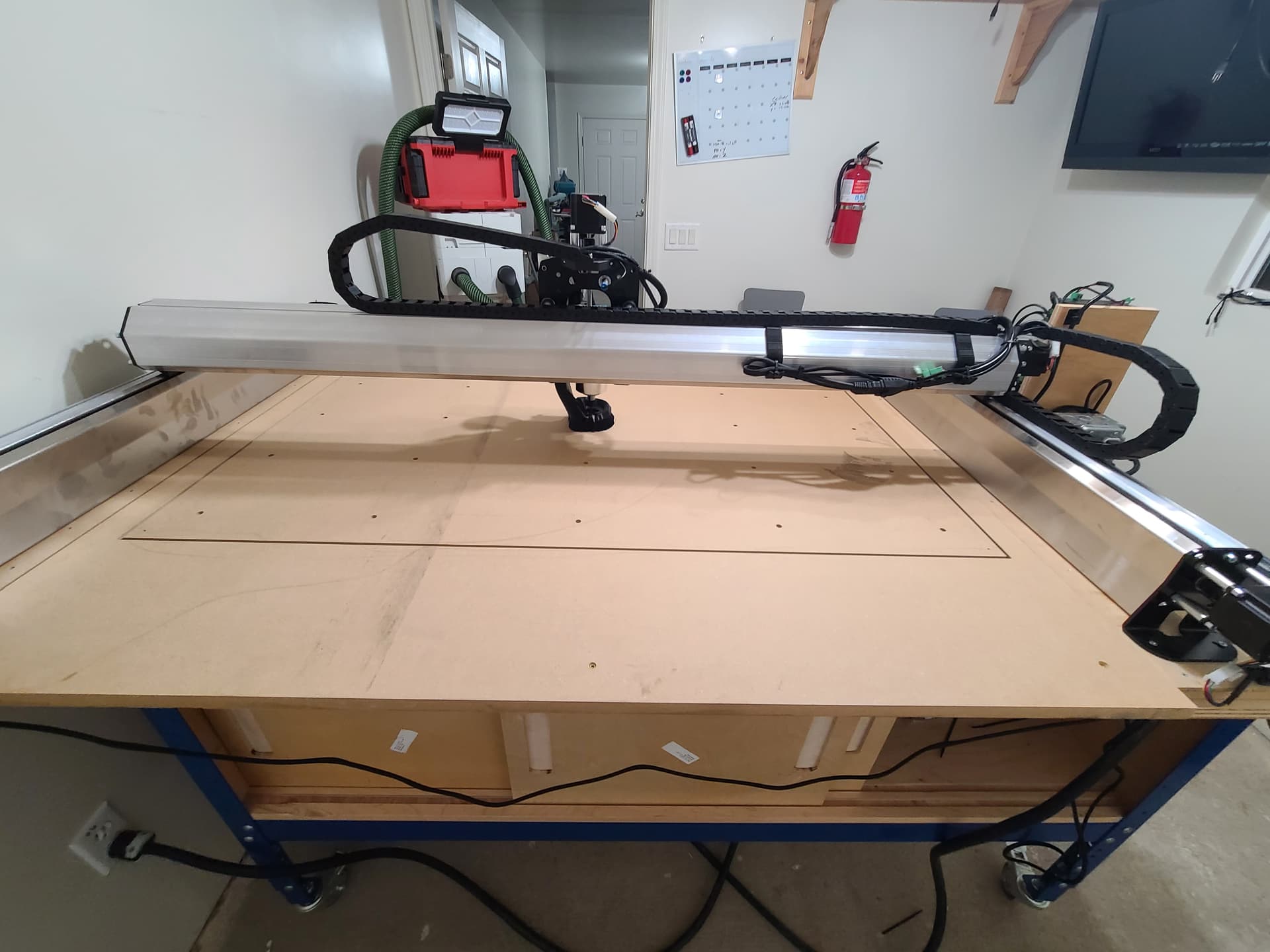
Edit: Off topic but I like your setup! This might be the first time I’ve seen a full sheet on a LongMill, those new machines are HUGE!
Edit2: I thought of a way to check the Z axis travel is correct. I’m assuming that you still have the sheet of MDF on the machine and don’t want to move it so that your cuts line up. Without changing the XY zero I would put another piece of material 3/4" thick on top of the MDF. I would then zero the Z on top of that. Then I would remove the new piece and carefully lower the Z axis until it’s just touching the original MDF. If you’re not at -0.75 or really close then somethings up.
Try loosening the anti-backlash nut completely on each axis. Sounds like you might have them too tight. Also make sure you really crank down on the tightening of couplers, especially on the X-axis.
The back lash nuts are all set at a neutral (or barely touching the plastic as they are all screwed in to just touch) as I had to take the CNC apart and remove the lead/ball screws to clean the oil I used off and then re-install and retune and re-tram and lube .
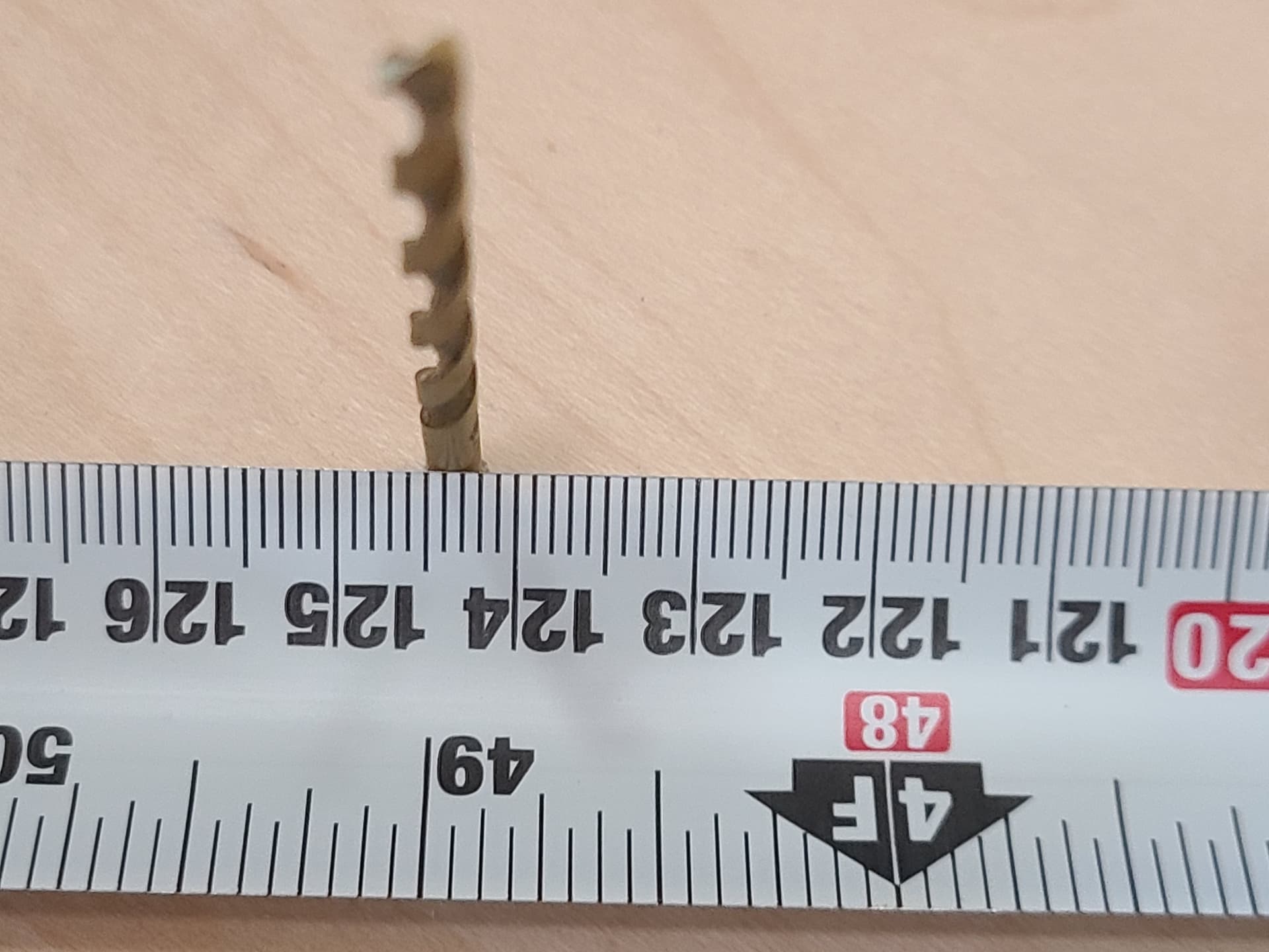
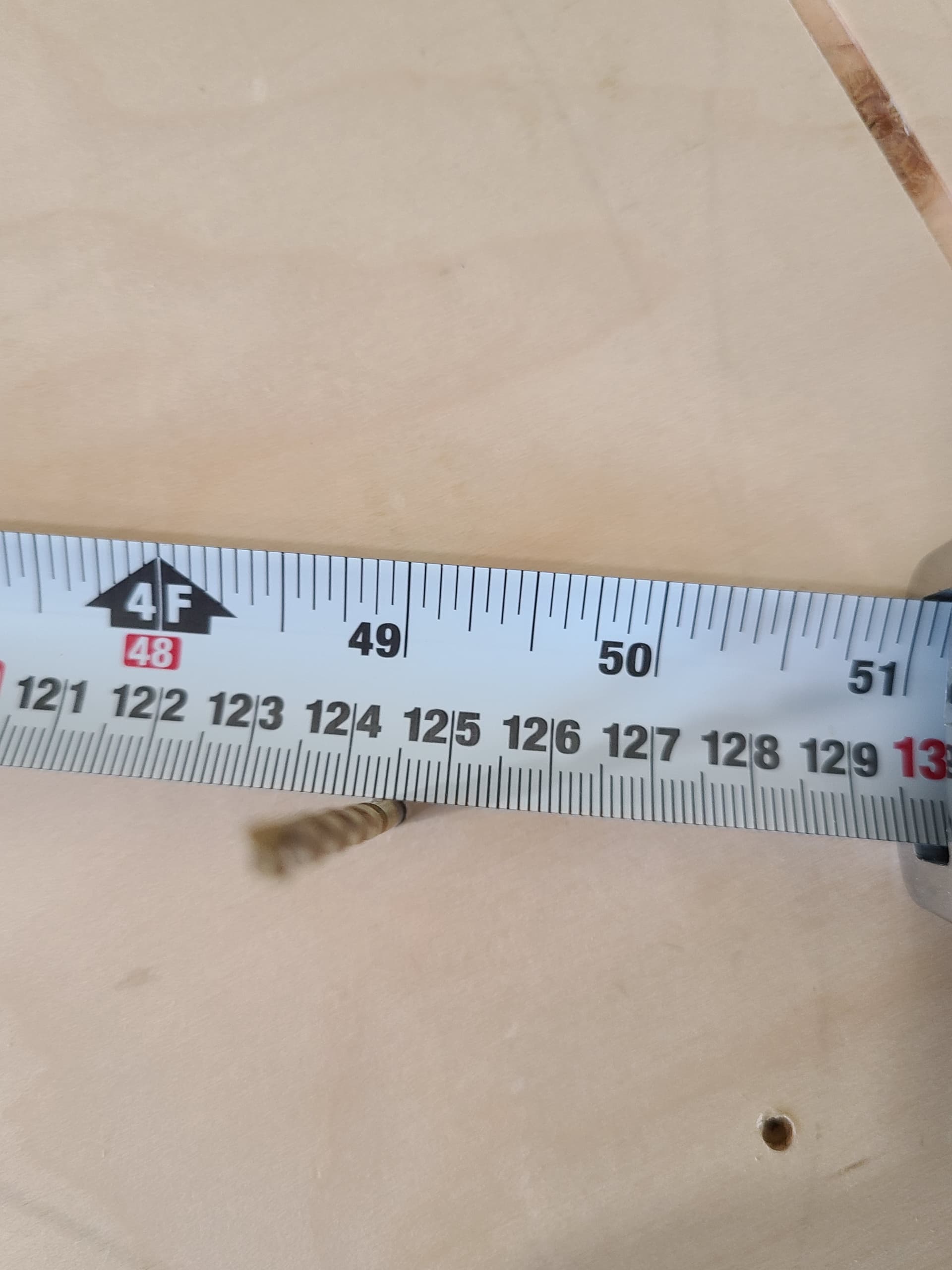
When I ran the square check or fit check gcode from IDC the gcode drilled 4 holes with an eighth inch drill bit and I put 4 drill bits into the hole then measured for square. See Photo
The diagonal measurement is124.5 left rear to right front , Right rear to left front was 124.5 telling me that my CNC is very square. Then again When I installed the rails I squared then using a 4 ft dry wall tee square before tightening them down x 2 (two squares in use one each side).
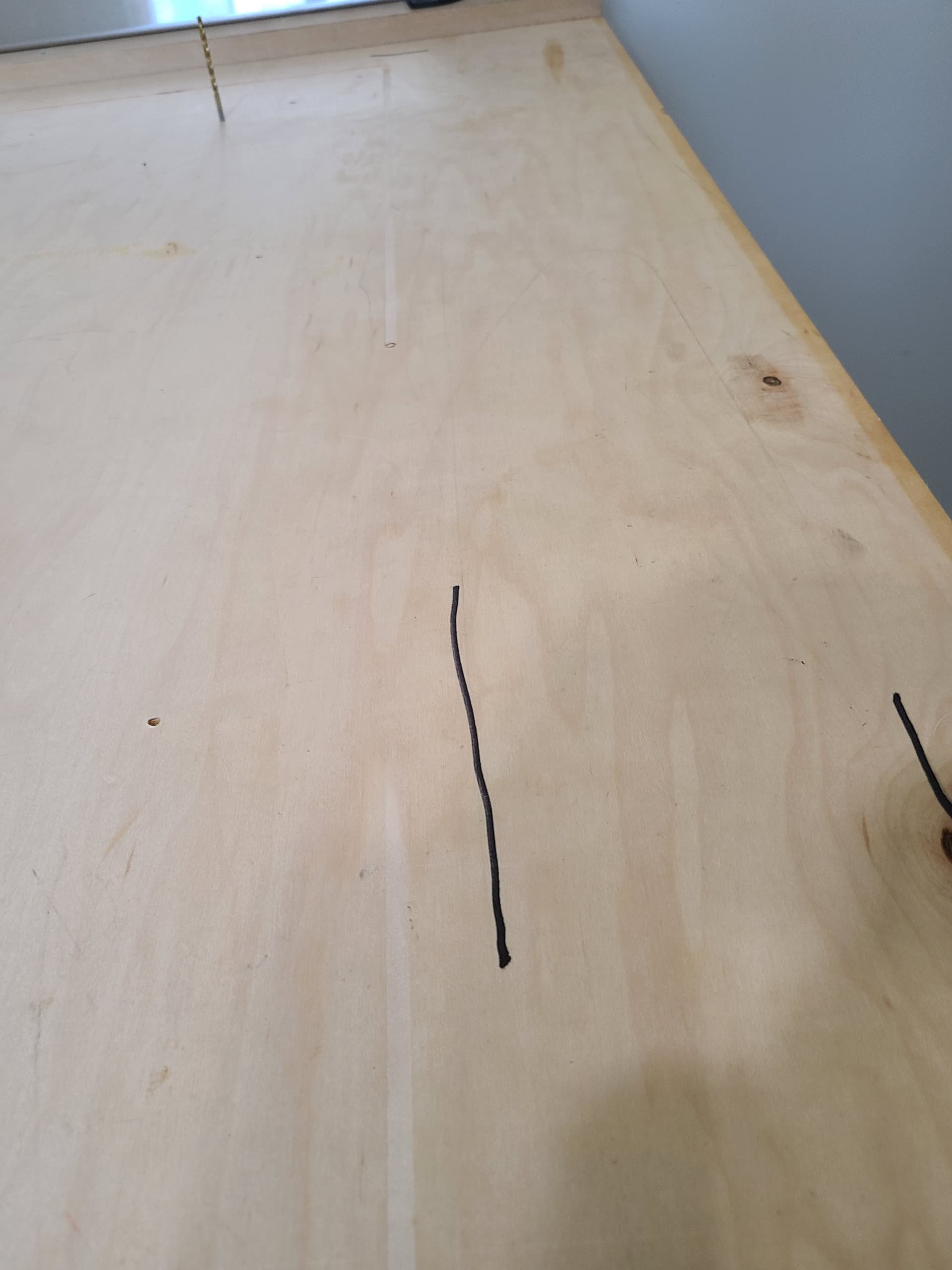
I checked that and had 1/4 inch of travel down before bottom stop on the Z Axis. I also readjusted the 3/16 Endmill downward and rezero the Z axis ran pass two and still no cut through on the right front corner of the spoil board. ( I messaged Garratt from IDC Woodcraft of the video linked in his instruction guide and Garratt instructed me to lower the z manually. As I am very green with the CNC after pass five and still no cut out I pushed pause in gsender, turned off router and used my hand to turn the ball screw until the bit touched the subbase and the restarted the router and hit the continue in gsender. Six pass did cut the remained but that is not how the CNC should be operated. This is what I was left with on the subbase see the three photos.
That should work.
Please never use drywall squares to set up a machine, notoriously not square no matter how many you use. I did modify one once, drilled out a rivet and bashed it on the floor to get it kinda square.
My tee squares that I use for drywall / and setup Bora saw rails (before I found Festool Track saw and Rails) in my own home are precision machined from a machine shop on their Industrial CNC. Plus I double checked with my Wood Peckers Squares to ensure squareness.
My wife says I am too much of a perfectionist when it comes to working on the house. If she only knew what I spent on the aluminum flat stock that I use on my woodworking jointer and planer from the same machine shop. I would be is serious trouble.
Yes after sitting idle for more than ten minutes gsender will not return to the same spot that was set to center of table and that the CNC was zeroed out at for the X/Y axis. After the run of the gcode the cnc will return to center aka zero X/Y and will be off by 1mm to 2 mm and I have to re-zero before either rerunning the gcode or moving to the next step within the IDC Woodcraft spoil board project. For the life of me I do not know why this is happening.
For the 49x33 cutout the cnc makes three passes each time plunging deeper into the MDF. I have ran so far the Gcode in Gsender 6 times. With the sixth time actually pausing the cnc via gsender and manually by hand lowering the Z-axis by turning the ball screw until the bit touched the subbase in an area in the cut out groove that I could see the plywood subbase. Then turned the router back on and hit resume in gsender. This is not the right way this machine is supposed to work but my level of frustration at that point is to just get it done.
Then this happened to me in step 5 The holes for the rivets did not cut all the way through the Right side. There is an issue with the CNC when it gets to the right side. Baffled at the moment.
Regarding your Edit my subbase top is a custom core ( according to the Hardwood/ Sheet goods raw material cabinet supplier the custom core is supposed to prevent warpage) sheet of Maple grade A cabinet plywood at 72 inches long by 48 1/2 inches wide and true 3/4 inches thick. It is 48 1/2 because I forgot to trim it down and the edges were so clean I left them alone until I edge band.
As for edit two unfortunately I took the spoil board off as I forgot a step at step 1 and did not seal the top and had to take it into the other part of my shop and seal it. Mistakes were made and I own them . which showed me that the cnc is not cutting all the way through the right side of the material and yes the spoil board was securely screwed down to the subbase with zero gaps.
Edit : I will provide a Sketchup file and a PDF with the Cut list from Cut List Plus FX for the work bench setup for the CNC , when I get some time to to renew my Sketchup license.
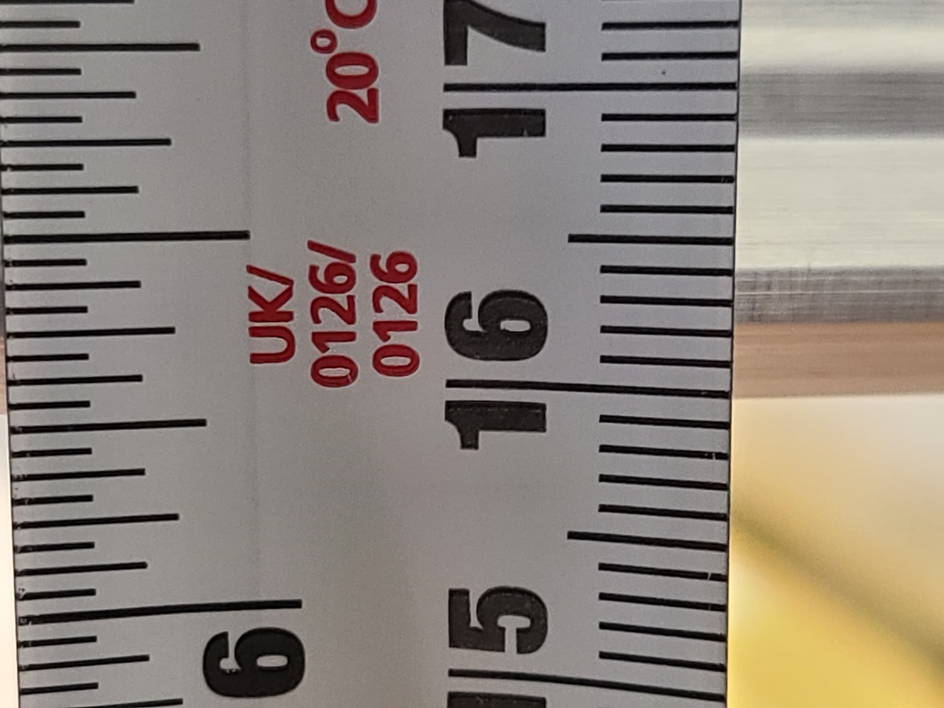
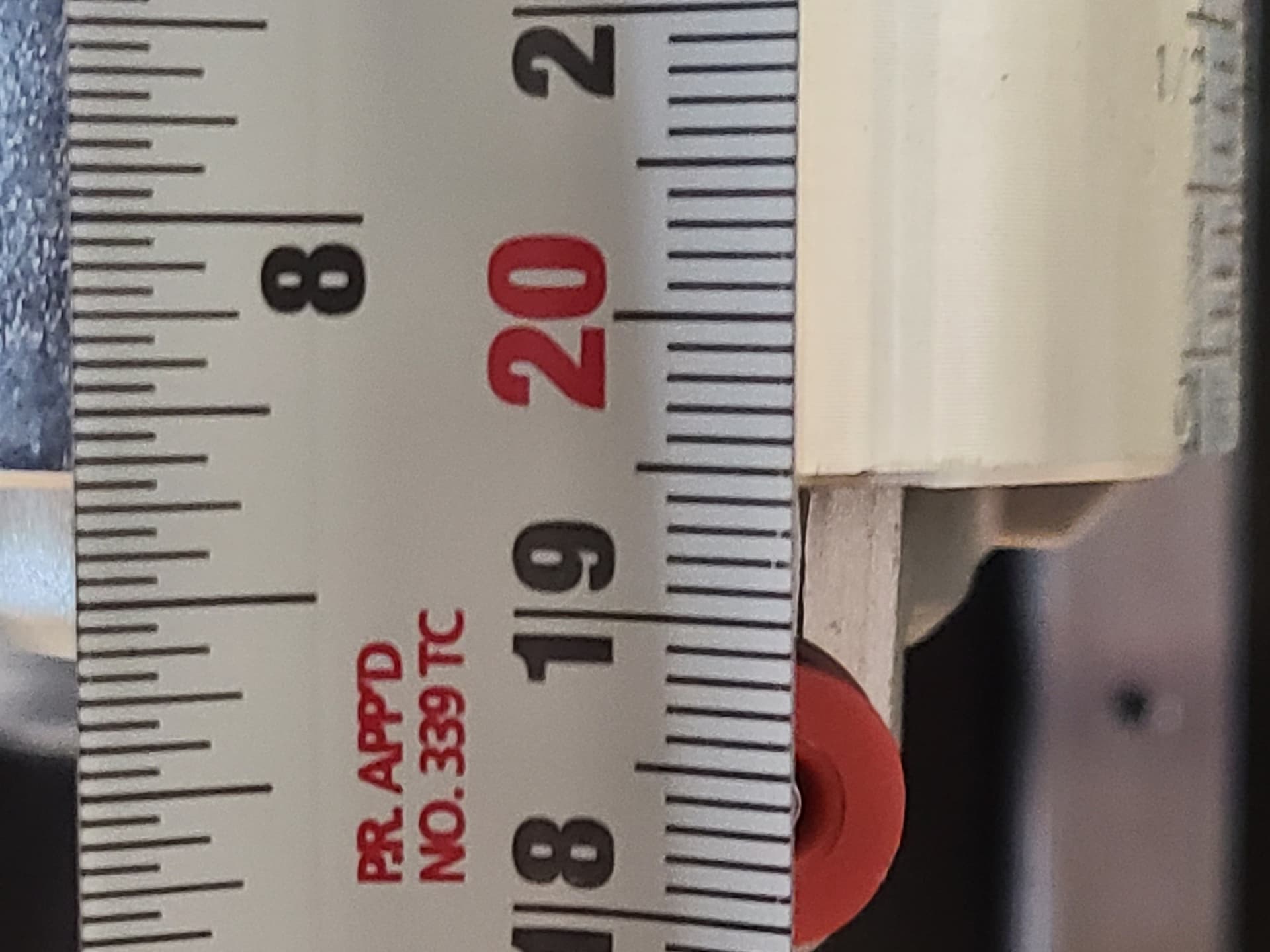
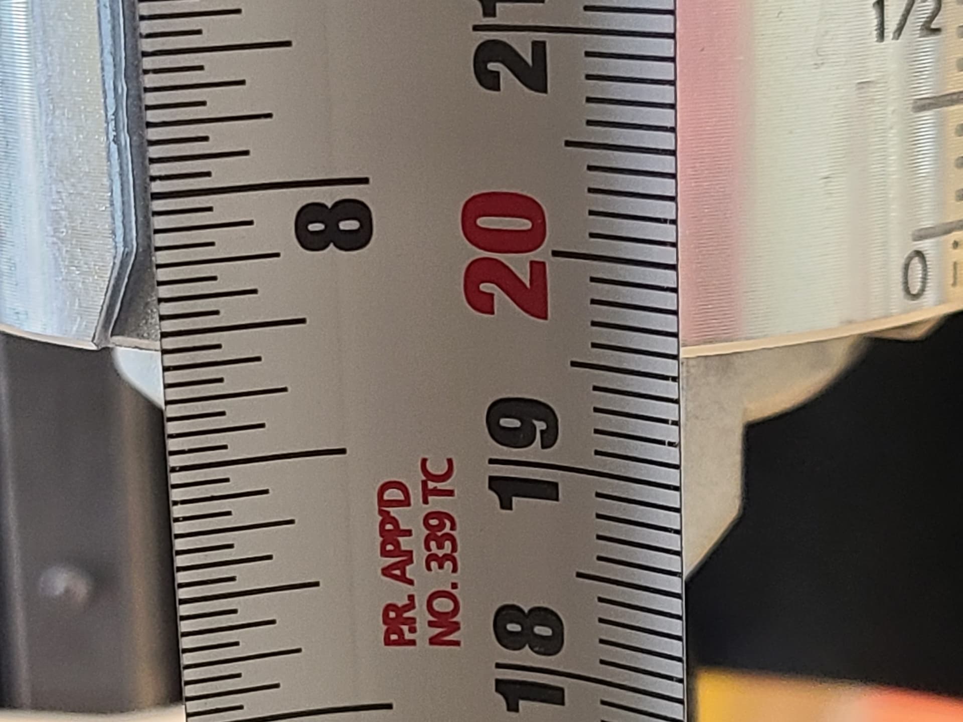
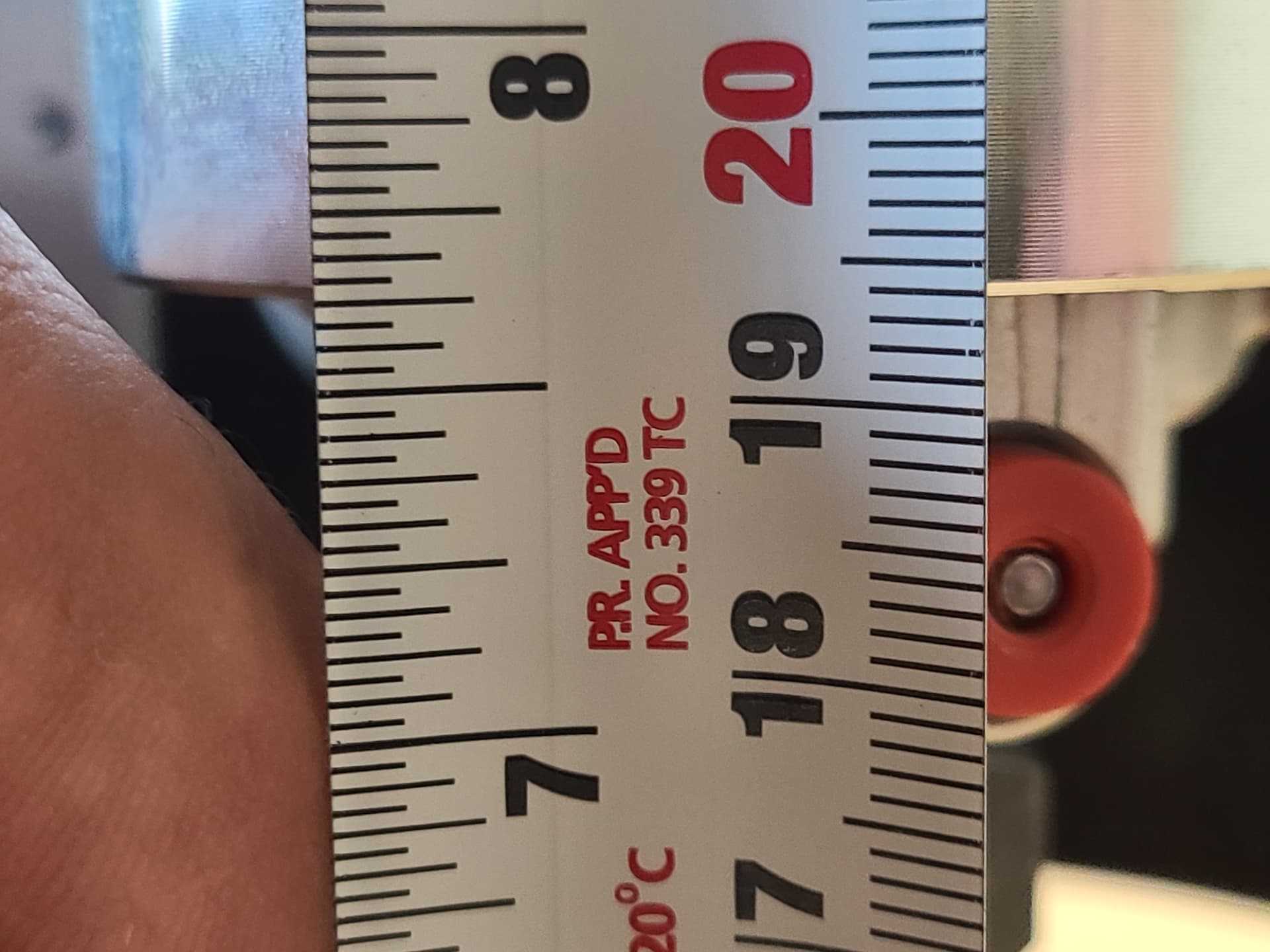
according to the video that is linked in the pdf the gcode does a Through cut with 3 plunging passes of the spoil board for the 49" x33" x 3/4" For some unknown reason to me the CNC running gsender does not cut fully through on the right side and after doing step five it appears the issue starts in the front center to right side after center point of the X axis. I have measured from the Z Axis at top stop to subbase and here are my results to the router bottom with the Z axis at the top stop I get 19.4 cm at the far left X axis and all the way forward of Y axis . From the center of the X axis still at all the way forward on Y axis I get 19.6 cm. From the far right of the X axis and still all the way forward of the Y axis I get 19.5 cm.
In summary there is a difference of 1 mm from the left side to the right side with a slight dip in the center of 2mm greater than the left and 1 mm greater than the right. The final cutting pass is at .8" on a .75" MDF board could that 1 mm be making such a huge difference being that 1 mm is equal to 0.0393701 inch and 2 mm is equal to 0.0787402 inch Reminder that the center part of the cutout cut through just fine it was the right front corner along the right rail from about 3 inches center to right and 4 inches right front to right rear. It is almost like the cnc is slightly lifting during cutting on the right side.
@Jwar I don’t know anything about the step numbers from IDC and I can’t find a link to them. However, I would suggest that you create a file of your own instead of relying on anyone else’s. In your CAD/CAM software of choice, create a square of any size you choose. Create a profile toolpath, cutting through the material. The number of passes will clearly be dictated by how thick the material and the pass depth of the bit you are using. Then, see if the Mill cuts through.
Check the flatness of your main spoil board. It may not be as flat as you think, or the underlying support of the table (torsion box??) may have some gaps causing a bow to happen
I can’t remember if the IDC file and instructions require you to surface the secondary board you are drilling holes into or not. If it doesn’t and your main spoil board is not flat, your cut-throughs will not be precise.
Since the issues seem to be on one side or corner, my guess is you have a slope in your spoil board, or the project wood is warped or the project wood thickness varies in areas around the piece (I find it hard to believe that the wood is a perfect 3/4" all the way around the piece. Not saying it isn’t possible just hard to believe).
The same for the main spoil board. Not consistently the same thickness, so there are low spots and high spots. You would need to surface your main spoil board
Check the thickness of the area where the bit did not go through the project all the way and see what the thickness is compared to where it did go all the way through. Use a caliper.
If it’s not the same, you will have to add a millimeter or two to the cut depth to get through the board - which will eat into your main spoil board, especially in the areas the board is high.
If it truly is the same, it’s not the piece that has varying thickness, but more related to the spoil board itself.
Update,
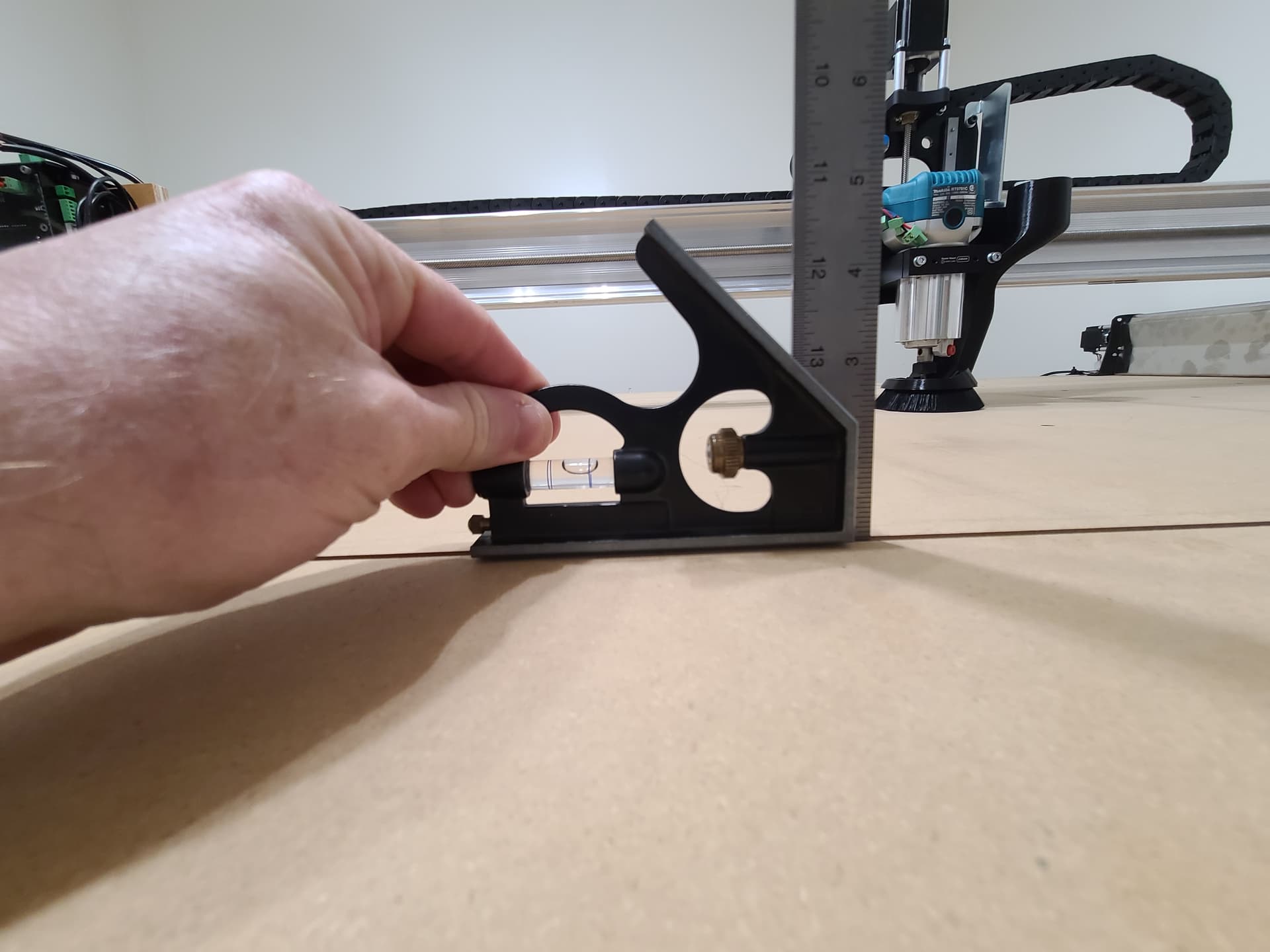
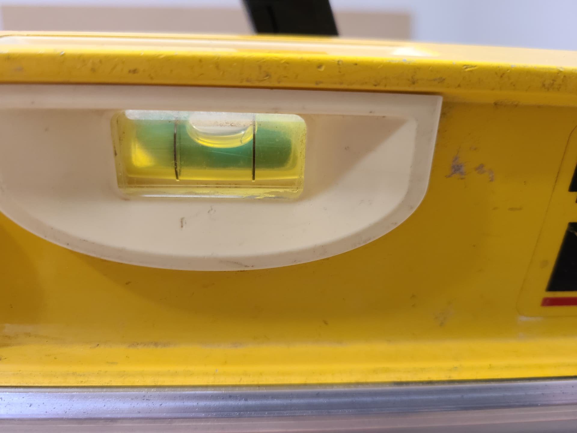
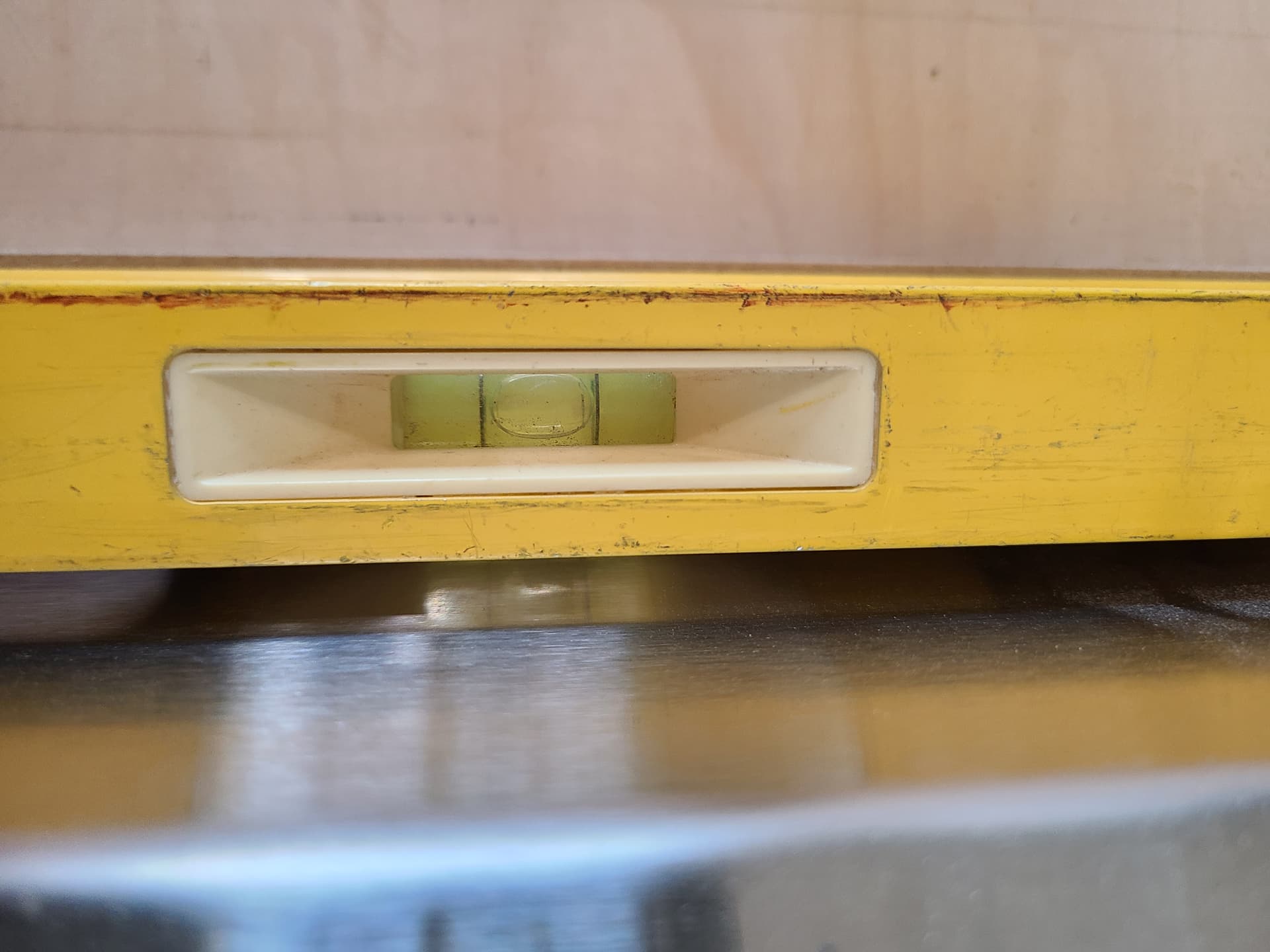
Rechecked level and my table is level front to back on left side, front to back right side and front to back center. Then I also checked the left and right rail’s subbase with a 4 ft level and both the right and left are level in the front to back orientation. Then I checked left to right on the table itself and across the tops of the Y axis right rail and Y axis left rail that too is level. I even checked the X axis gantry for level. Only issue I found is 8 inches from the right rail towards the center is a gap under the level I used a multiple feeler gages and measured .031 inch. See photo previously uploaded labeled Right Rail with groove after six passes step 4. This would account for the variance in height from the table to the X axis gantry bottom. Yet As I see it table is level with a slight dip (.031 inch) in 8 inches from the right rail front towards the center. I am going to rerun the G Code and watch what the Z axis does. I used a caliper on the mdf and the MDF prior to seal coat on the bottom was .75 now the reading is .76 and that measurement is consistent all four corners and all four centers. Sheet of plywood that is the sub base is .75 also
It sounds like the plywood is not perfectly flat which is to be expected really. After you mount and surface the spoil board all should be good as you are very close to flat and have been really meticulous, not a bad thing, so far in your assembly. That’s my two cents anyway.