Matching profiles of mating parts

Hi Michael, thanks for your reply. So ya I am trying to make something similar to what your picture shows. I have attached some pic’s which should give you a much better idea then my explanation. I’m thinking that some sort of off-set is the answer but I’m not 100% sure of how much, seems to make sense the offset would be either the full cutter width (1/4) or half the width dependent on where the toolpath runs. Where did you come up with the 1mm offset on your piece. Anyways if you can have a look at the pictures attached and send along any additional comments or thoughts it would be appreciated.

Hi Ed, thanks for your much welcomed reply, I have attached a few pictures, as for the size the end caps are approx. 4.5x11 and the main board is 14.5 x11. The arcs are orientated the same way when cut. After some frustration I did a test cut, I took the tool path and a single board, ran it hoping that I might use the two pieces as templates for a flush trim bit on the router table. The pieces did not fit, so I’m figuring I have to compensate for the ¼ end mill, but I’m not certain.

Anyways I hope the pic’s will explain a little better of what I’m trying to do, thanks in advance


Thanks for your reply Grant, I’ve watched some of Stubbs video’s ( at least I think that’s his name) in the past. I believe I see the problem that being I have to compensate for the ¼ end mill bit. So as I see it cutting 1 piece on the outside of the line and then off setting the second piece by ¼ should produce what I’m trying to accomplish. Would you agree

I just pulled it out of the air, that curved piece was my first non-practice try. Maybe an even smaller offset would work better? I think I am on the right track with the offset method, but we always think we are on the right track or we’d be trying something else, right!

The video that Grant linked seemed like a good way to do it but I’m not sure how to translate the router table method to a CNC machine.

Ya the video Grant linked was good. I’m thinking if nothing else I could make the templates on the cnc and then cut the profiles on the router table using the method in the video. Not giving up on doing the matting profiles on the cnc just yet,

I might be stretching my knowledge a bit here, since I usually use Fusion 360 - but typically I would model this as two mating parts, and the tool offset would come in automatically in the toolpath generation (based on the radius of the 1/4 inch bit itself). I would expect any offset error to come from any differences in the nominal bit diameter vs the actual - and measure it with calipers to adjust.

Thinking about it - the tool offset needs to be a radial offset (that is, perpendicular to the tangent to the curve at every point), as opposed to a linear offset (i.e. offset in just the X or Y dimension). In my head, that would probably cause the effect you are seeing.

Sorry I can’t be more helpful with VCarve Pro - I’m not familiar with how it generates toolpaths.

I think the free version of Fusion 360 can still do what you need (2.5D milling) according to this: Changes to Fusion 360 for personal use | Fusion 360 | Autodesk Knowledge Network

The learning curve for Fusion can be really huge, but it might be worth investigating for specific needs.

Good luck!

Thanks to all that replied, much appreciated and it has certainly given a better understanding of the problem and corrective solution(s). I plan on somewhat starting fresh making new end pieces and using a combination of your suggestions on some test pieces until I get it right. Will post with my results one way or another, here’s hoping their positive results.
thanks again B

@Brunom I apologize for the long delay in adding to the discussion. I have an idea on how to do this, but I will try it in the shop before posting - to save me the embarrassment of being wrong. I hope to do that early tomorrow and will post my results.

@Brunom OK, finally, I got this done! I see that you posted on the Vectric forum, too and I’ve posted my successful project on there as well.

I’m attaching two screencaps of the tool paths that I cut. The two pieces mate perfectly. A couple of things that I found:

  1. The actual diameter of my “1/4” downcut end mill was not .25". It was .2460". Not a huge variance, but enough to make a difference I think.
  2. When I was doing the test cut to find the diameter of the bit, I noticed that, when taking more than one pass, there was a very slight ridge or step in the groove. When I repeated the test cut in only one pass, there was no step (duh). Clearly, if you are taking more than one pass - and that is a must on thick material - there is a chance for bit flex, machine flex, etc, that could throw off the arc by a very small amount.

Anyway, FWIW, there is the solution. I don’t believe that there is anything more that I can do on this, but if any of this is not clear, post back.

sheet 1 _ male

sheet 2 _ female

1 Like

Glad that worked out Grant and I hope that’s all @Brunom needs to do. I’m now wondering if it makes a difference if you have one curve vs multiple curves. I cut the pieces in the photo like you did, one cut on one side of the curve and one on the other. As you can see they don’t fit well at all. I think the problem is the farther the angle of the cut deviates from the main direction of the cut the more it binds. For example in my photo the main direction is vertical and it’s where the pieces go fairly close to horizontal that they touch first.

Maybe I did something wrong in my test and I might try to it again. If you have time and scrap maybe you can try it too. Please don’t waste any good wood on my account!

@_Michael Were both of those cuts done from the same board?

I’m not sure, probably not as I picked them from my scrap box, they are the same thickness.

Edit: I found a thin piece of plywood scrap and I will run the test using the same board.

@_Michael Running them from the same board may be the problem, Michael. By that I mean that if you are doing that, you need to have the design drawn twice. I did my test on the same board, but drew the arc, then copied it, then created the toolpaths - one on either side of the line. I did not try to offset at all.

I hope that I’m making myself clear. When I get time, I can try your design, but I’m pretty confident that my “process” will work.

I think I understand your “process” because it was my first though on how to do it as well. I ran the test again and got the same results.


As you can see they still touch at the ~45 degree part first. Believe me, I really wanted your process to work because it is simple and simple is always better if it works IMHO. It was these results that led me to try the “offset method”. I think of it like needing a tolerance, like when I do dovetails, the pins need to be slightly smaller than the tails in order to fit.

I cut these with a 1/8" or 3.175mm bit with a 1.4mm pass depth at a speed of 17mm/sec or 40inches/min which I believe to be conservative.

So next I wanted to get a bit adventurous because I’d like to be able to mate different shapes, whatever I want is the goal, like the vase with two faces etc.

Using the same stock left over from the first test. The new line on the left is the original. I offset that line by .15mm to the right. I then moved the offset line to the right.

Then I cut them out without resetting any zero’s, oops wrong thread! :grinning:

They fit but a little to tight, I think a little bit more offset was needed.

Looking forward to seeing what you, or anybody, can do with this stuff!

@_Michael A lot of this is trial and error. I’ve done several jigsaw puzzles and I use an offset to get the pieces to fit snug but not tight. The offset changes depending on the thickness of the material. I guess it’s just a friction thing.

I had some time to draw up what I think the problem is, by what I’m hearing - haven’t been out to the garage to cut anything, but this looks to me like the issue that is happening.

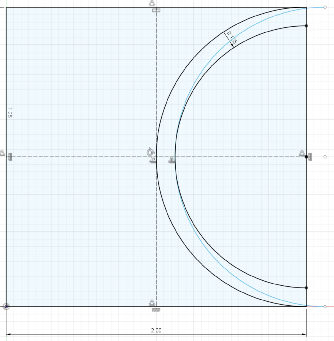
In this sketch, you can see a base curve (the left one) and two “offset” curves - one is offset radially by 1/8 inch, one is offset linearly by 1/8 inch.

Since I use Fusion, I don’t know the process for determining toolpaths that you are using - with Fusion, I select the feature and the bit diameter and it does the rest to determine what path the bit should take. You can see in this case, the path that the bit needs to take is a radial offset (that is, the diameter the toolpath actually takes is different than that of the feature we are dealing with). If we were to offset only linearly (that is the blue line, which has a 1/8 offset in the x dimension), you can see the bit follows the same arc as the feature (the left black line), but because of the bit’s diameter, the cut ends up having a different shape.

Can someone confirm that my impression of how your toolpaths are being created is correct? I can confirm 100% that Fusion would cut the right hand black arc, resulting in the shape of the cut that you ultimately expect. This would then cause even more issues for more complex and variable shapes.

Hope that leads to more success - and I do want to get into the garage, but we just had a new arrival and things are of course busy!

1 Like

So I just finished my second set of test cuts utilizing Grants process as detailed in his above post, I have to say the pieces fit flippen amazing on both tests, I mean perfectly, so hats off to Grant for coming up with that.
My 1/4 end mill was out also, made the necessary adjustment for that and the rest was somewhat easy once I got my head around it, basically using 1 vector for two cuts on two pieces of material. Tomorrow will be the real test on the actual pieces of walnut & purple heart I will post my results, positive ones I’m sure with some pic’s if all goes well.
Thanks again for all who provided their help, much appreciated.

@Brunom I’m glad that it worked. Keep in mind, though, that this was a solution to address your specific problem. As others here have said, if the profile of the cut changes, you may need to look further. For example, when doing jigsaw puzzles, the simple approach to your issue will not work. You must build in some tolerance/offset or the pieces will not fit together. It’s the same concept when trying to put a 2" peg into a 2" hole. Can’t be done. If you want to read more about the concept, looks into interference fits vs clearance fit. For jigsaw, we need a clearance fit.

Be sure to post your end result.

A post was merged into an existing topic: Celebrating a New arrival