I wanted to share how I set up a homing cycle using limit switches for others thinking of doing this. I want to say this is how I set up my machine and yours my vary slightly but I will include the stl files for the limit switch holder and the mounting blocks that I derived from the longmill part files so you can customize the switch distances based on your set up. Please be prepared to make necessary changes based on your machine and set up. I will not have time to walk people thru the process but will try to answer questions when I have time.
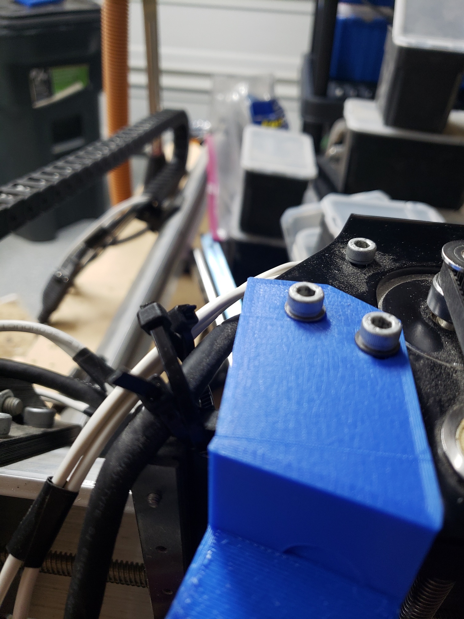
I created some 3D printed mounts for Temco lever limit switches on my X, Y and Z axis. I started by using a switch mount from Thingverse and downloaded the stl files for the Z gantry plate and Y axis plates to create the mounting blocks from. I then thickened and cropped the mounting plates and moved the switch mount where I needed them to be located. I ended up with mounting plates that located the switches where I wanted them and the mounting holes lining up with the longmill plates I was going to attach them to.
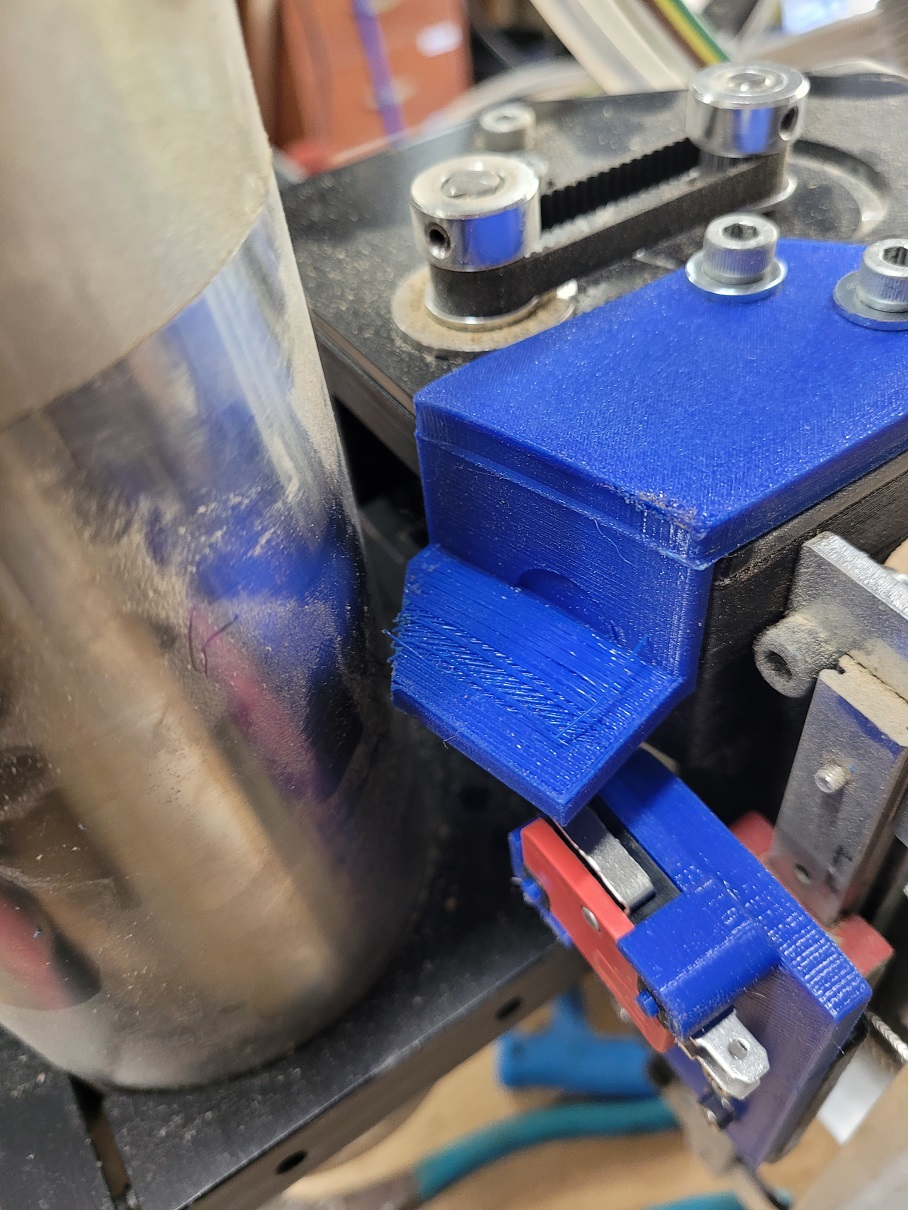
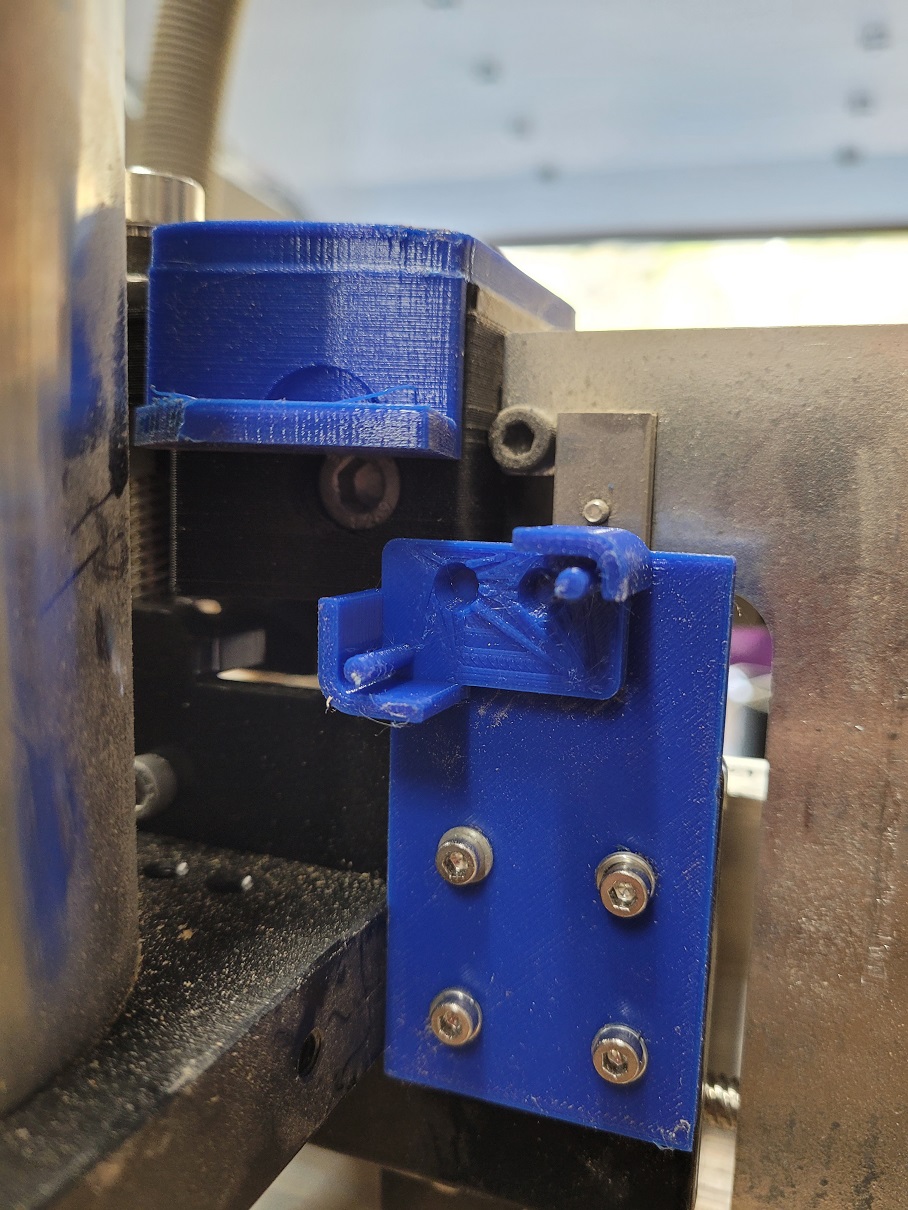
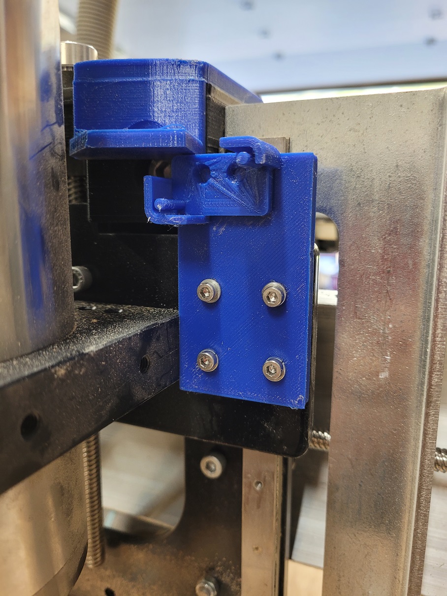
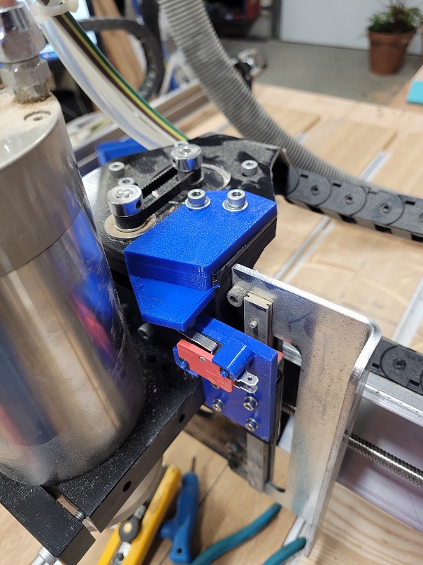
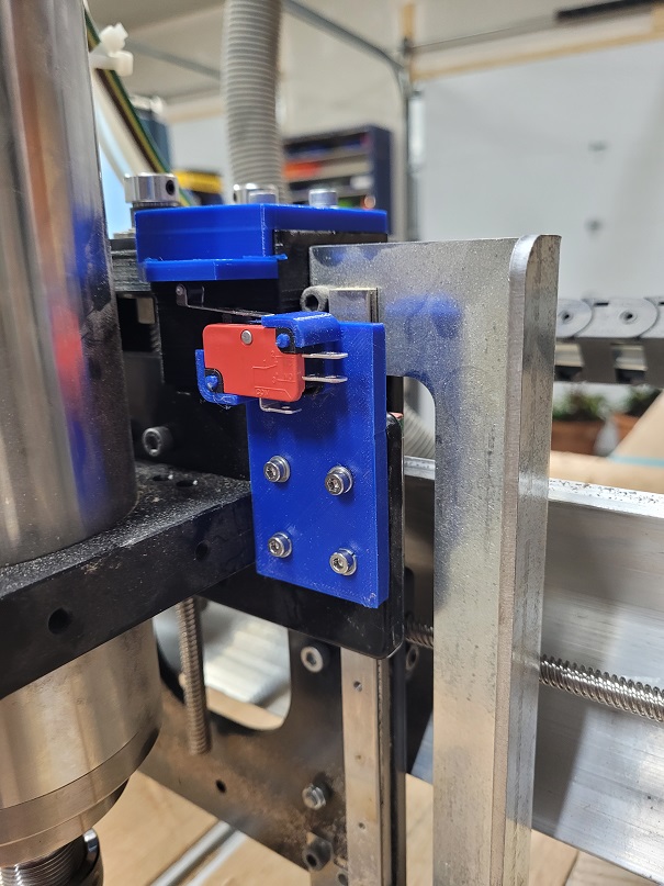
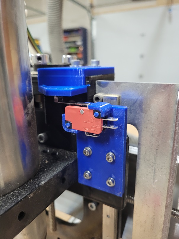
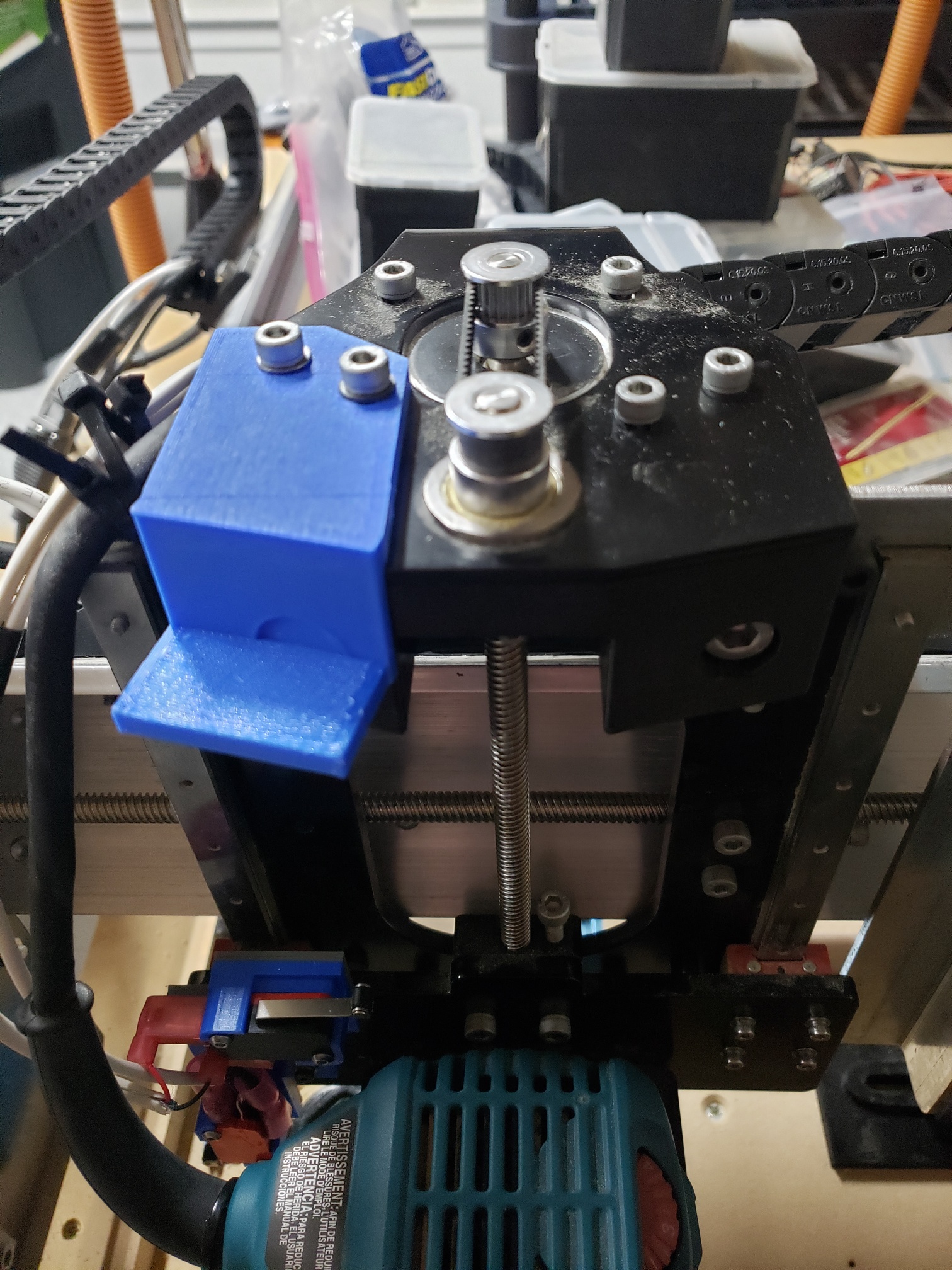
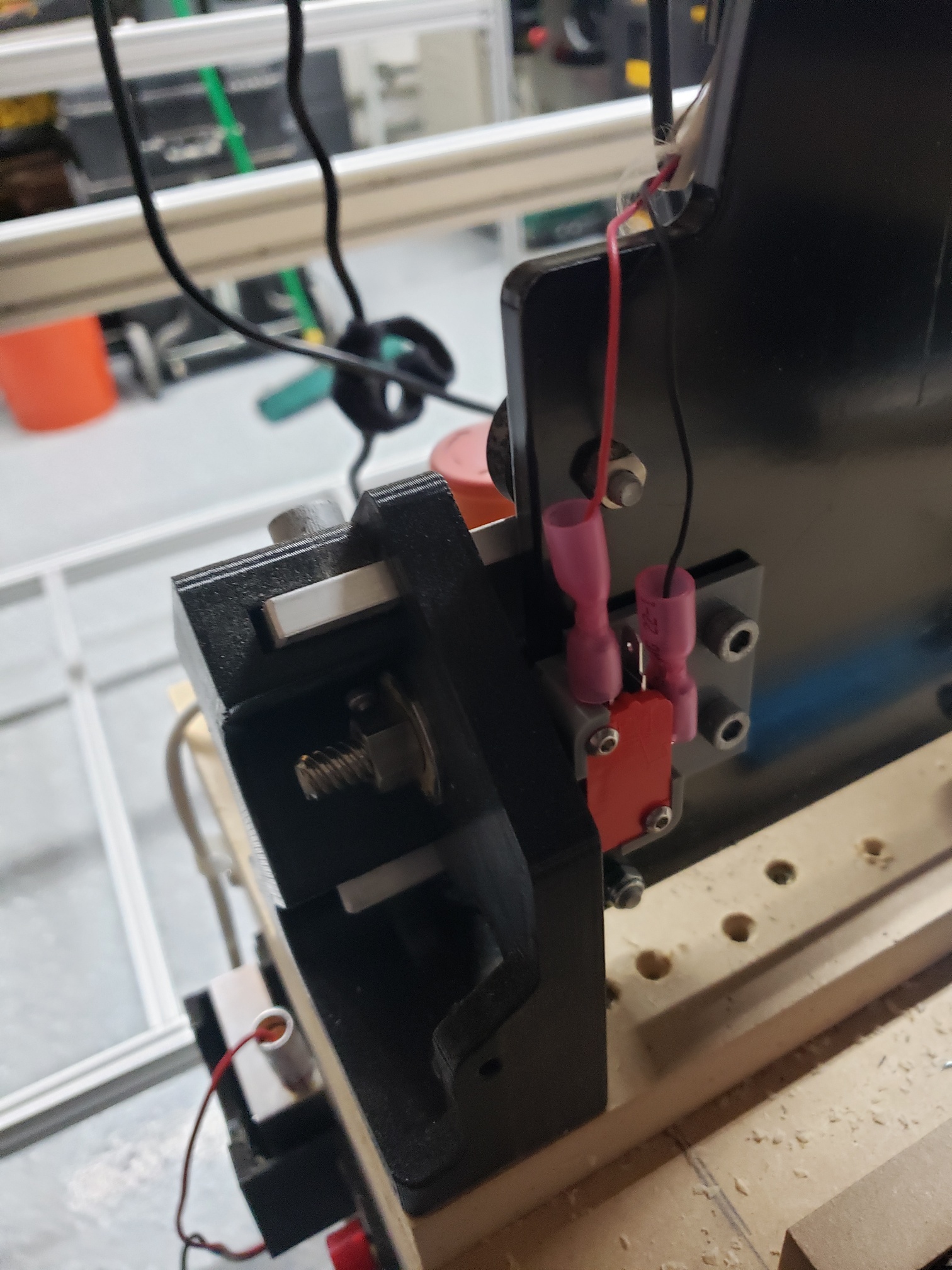
Since I wanted my homing 0,0,0 to be in the front left corner of my machine I attached my switches to the left Y axis plate, the x axis switch to the left side of the z gantry plate and the z axis switch to the right side of the z gantry plate.
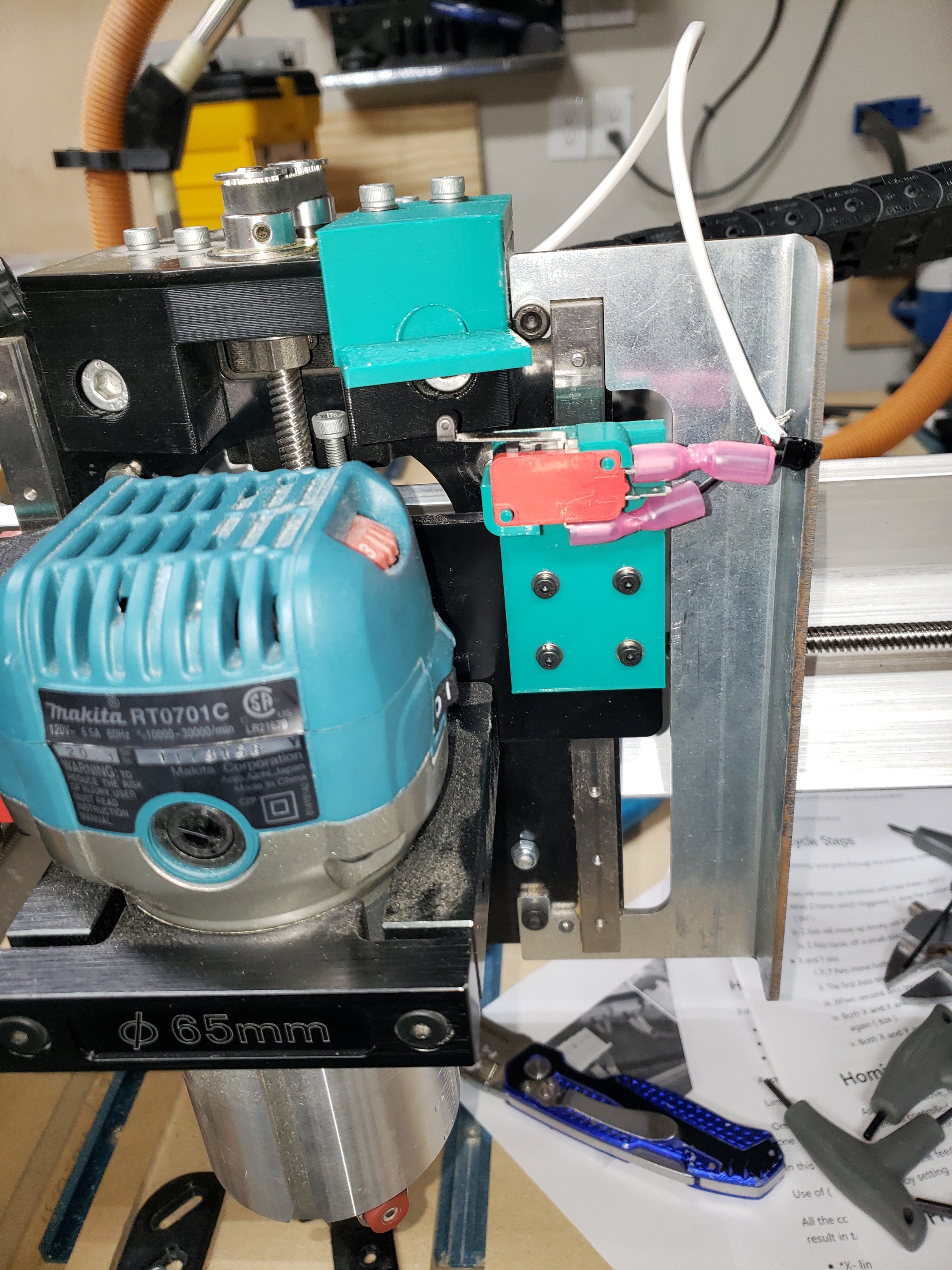
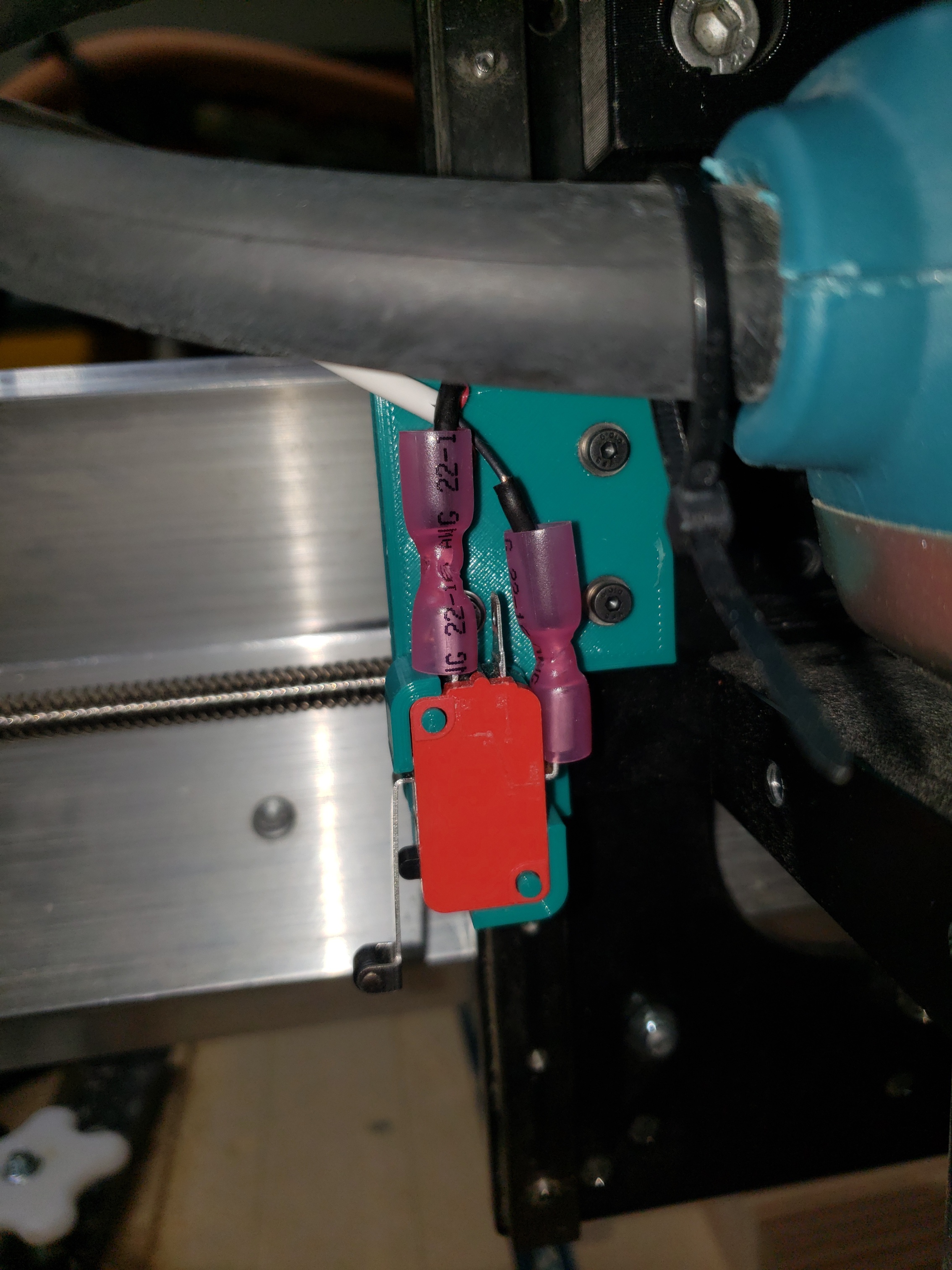
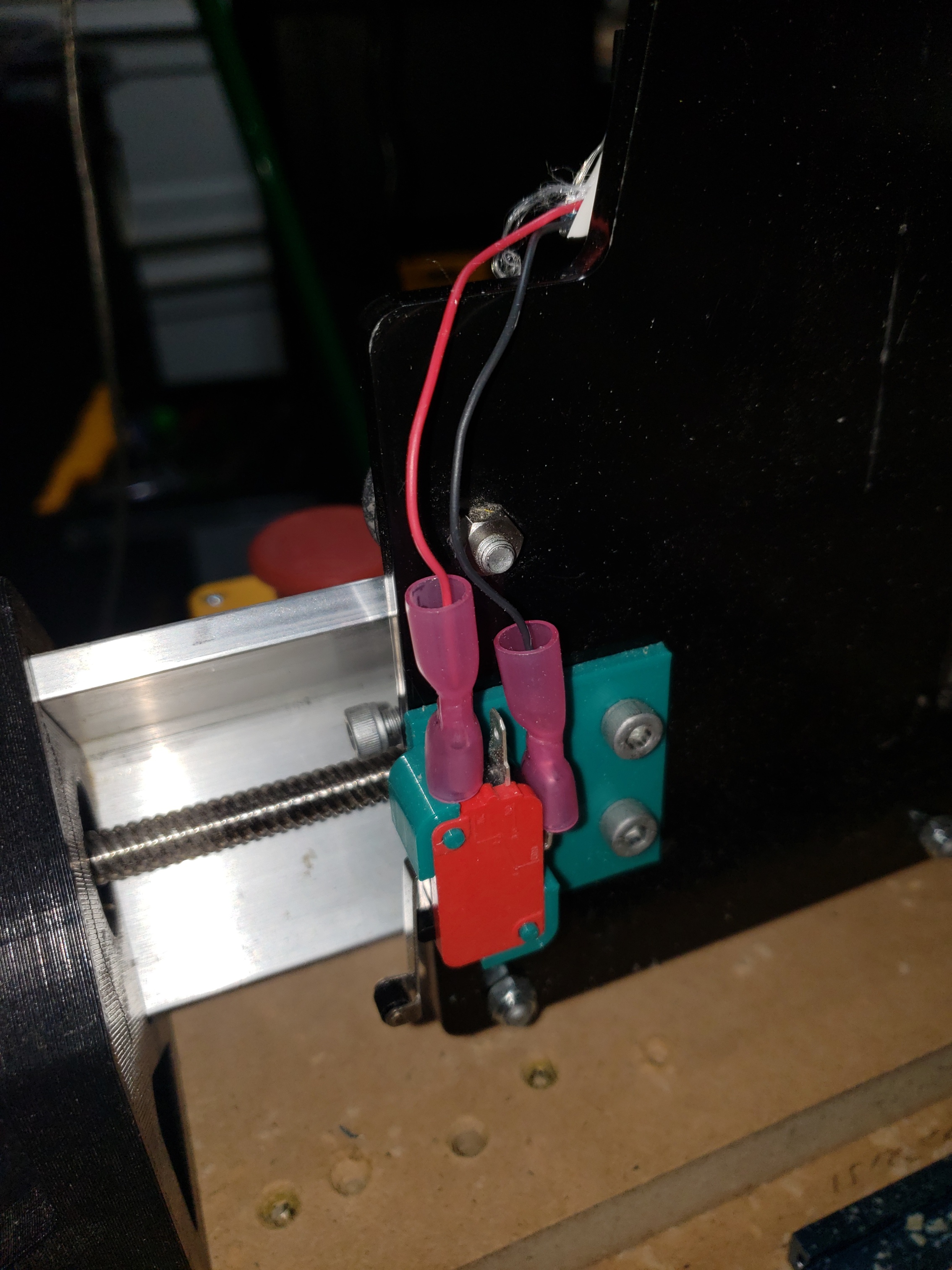
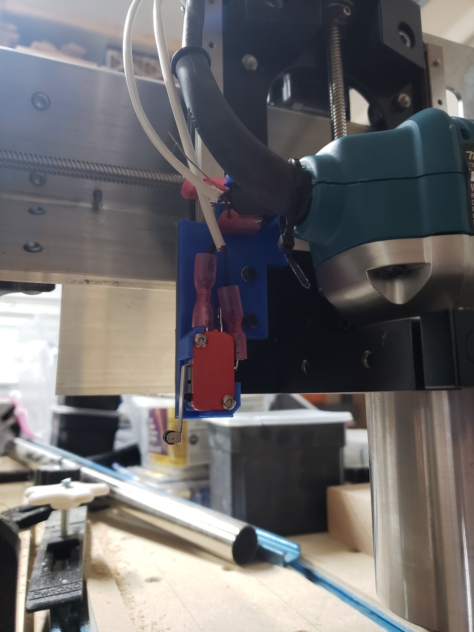
I used longer 3mm bolts and washers to attach the brackets to the z gantry and used the stock bolts for the backlash block for the y axis bracket. I left my metal bracket from magnetic dust boot to protect the exposed wire connectors on the z axis switch from getting smashed on the right side y axis plate. If you don’t have this or still want to use your magnetic dust boot you will need to move the z axis switch some. For the z axis I also created a bracket with a block for the switch lever to contact before I hit the upper limit. I mounted this bracket on top of the z axis bent motor plate and uses two stock bolts from that plate. I used some sticky glue to help hold the switch in the brackets in case vibrations might cause them to move up out of the brackets. It has seems to work and hold up after my testing.
After getting all the brackets mounting and the switches installed. I worked on my wiring. I used 2 wire 22 awg shielded wire. I wired the switches using a NC configuration where one wire connected to the NC connection (red) and the other to the COM connection (black) on the switch. I wire these connections to the limit connection (red) and Ground connection (black) in the controller using the XH 2.54mm connection ports.
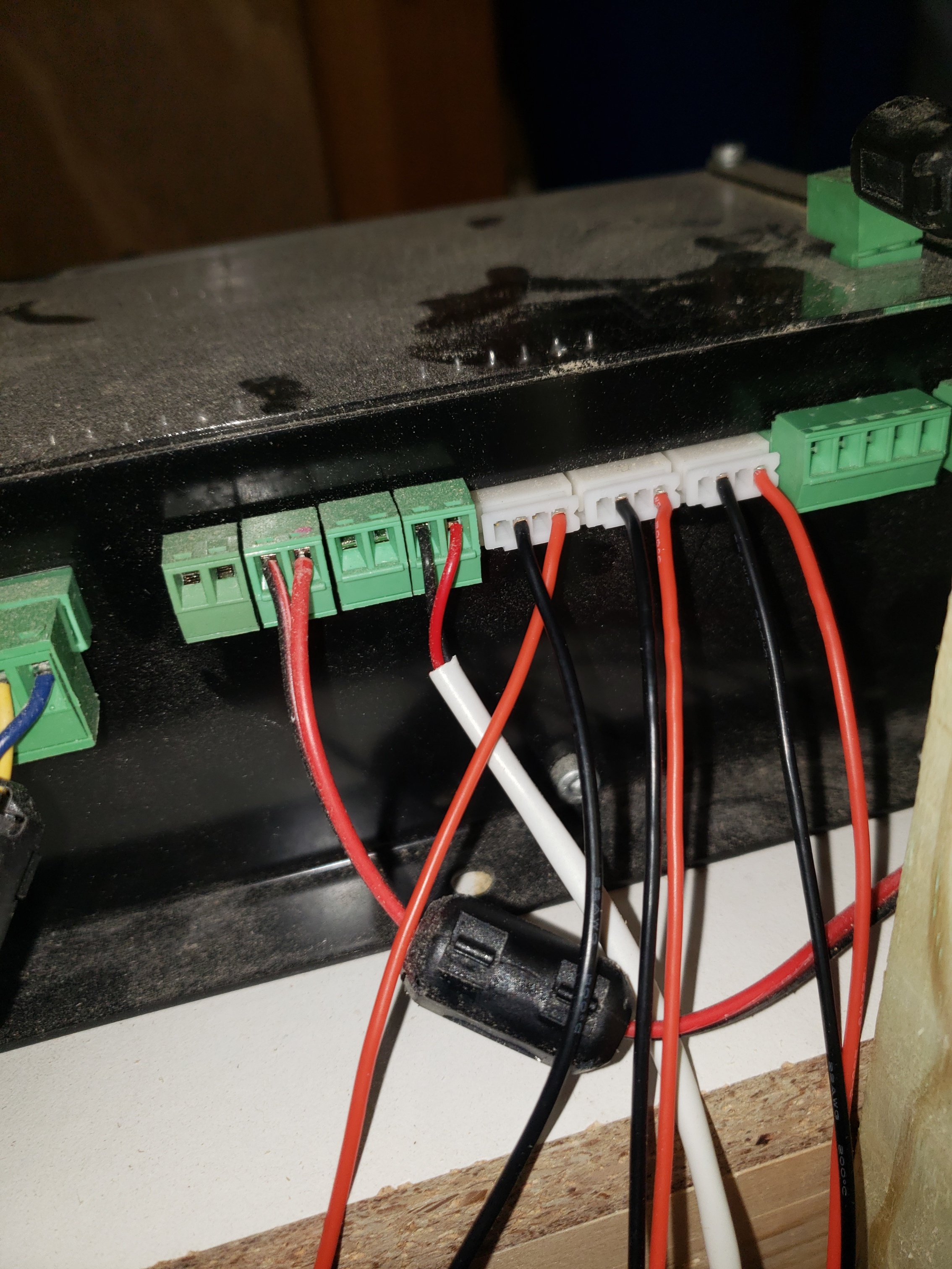
I also wired in .47U Capacitors before the connection to the controller to help control noise.
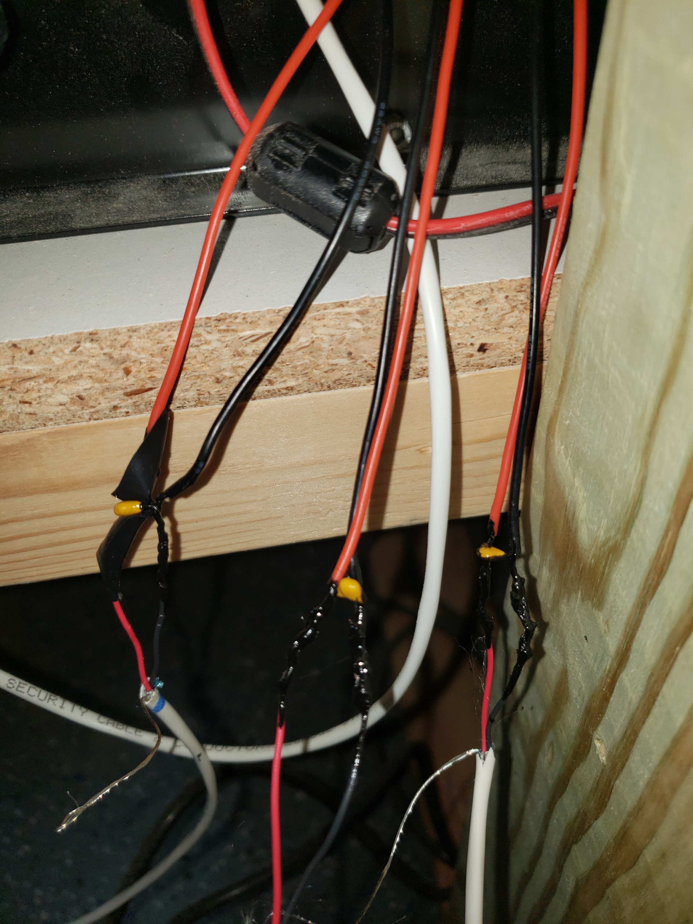
I’ll put the parts I used in the parts list below. I ran the wires thru the drag chains. I will also be attaching the drain wire to a ground connection to help direct any electrical noise away from the switches to eliminate false triggers.
I then adjusted the machine parameters after connecting the machine to UGS. The initial changes I made are listed below. This will move the machine to the left front corner with the z axis all the way up and then back the machine 1 mm off the machine zero after making switch contact.
Changed to:
$5=1 because I wired as NC on the switch
$22=1 enable homing cycle
$22=3 set front left, z all the way up as finishing point
This will set up the ability to home the machine to the same point at the left front corner of the machine. A note when you turn on UGS after doing this it will show an alarm you have to unlock. I believe this happens as a safety measure so the machine is not moving when you first make a connection. After hitting the unlock button you can press the home button and the longmill will move the z axis up first till it makes full contact and then back off 1mm and then move the x and y directions simultaneously until the switch makes full contact and the backs off 1 mm. The machine backs off 1 mm because of the homing debounce setting which is set by $27 in the parameters.
This will be your repeatable machine zero location.
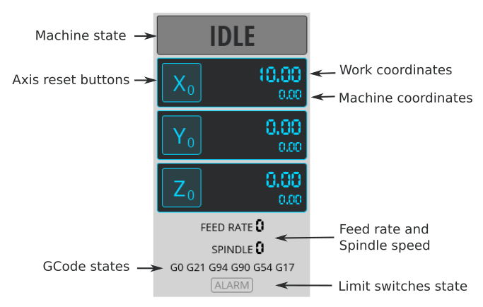
Your machine coordinates are the ones you are going to use when homing your machine. These numbers stem from your axis max travel and the location of your starting point. My settings are all negative as the left front of the machine are negative values based on how grbl is programmed. The z is negative because of the debounce value of 1mm.
Your machine coordinates should be X= -811, y= -811, z= -1. assuming your max travel settings are stock.
the stock longmill epprom settings
$130= 812 x axis max travel
$131= 812 y axis max travel
$132= 105 z axis max travel
(*You can adjust these numbers if you want to if your travel distance is different for some reason.)
So these will be the numbers you will work off of as these should always be constant. If you home you machine 1st and move from there you should always be able to get back to any location you have moved to. Once you zero your machine to your work piece which will set the zero for the work coordinates but you will also notice that the machine coordinates have also changed from the machine coordinates you had early. Make a not of these coordinates and if something happens such as program freezes, lost of power, etc you can always home the machine and then move the machine to those machine coordinates when you had zeroed to the work piece.
I hope this helps others if they decide to set up homing switches. If someone sees an error in my description please let me know and I can make the changes. I have added the stl bracket files to the longmill facebook group. It is in the file section and called “limit switch brackets.rarr”. Delete the extra “r” from the file to be able to extract the files.
Parts I used
3x Temco Micro Limit Switch Long Roller Lever Arm - found on amazon
2 wire 22 awg shielded wire - found on amazon
8x longer 3x.05x16 mm bolts for z gantry brackets
8x 3mm flat washer
8x 3mm lock washer
3x XH 2.54mm wire connectors - found on amazon
3x .47uf capacitors - found on amazon