I’m experiencing an issue where my machine isn’t cutting perfectly straight lines. I’m reasonably sure this is a new fault as I have some fence cutouts I made when the machine was new and these appear to be straight. I recently ran a rather lengthy and taxing job which I suspect has loosened or worn something but I cannot figure out what.
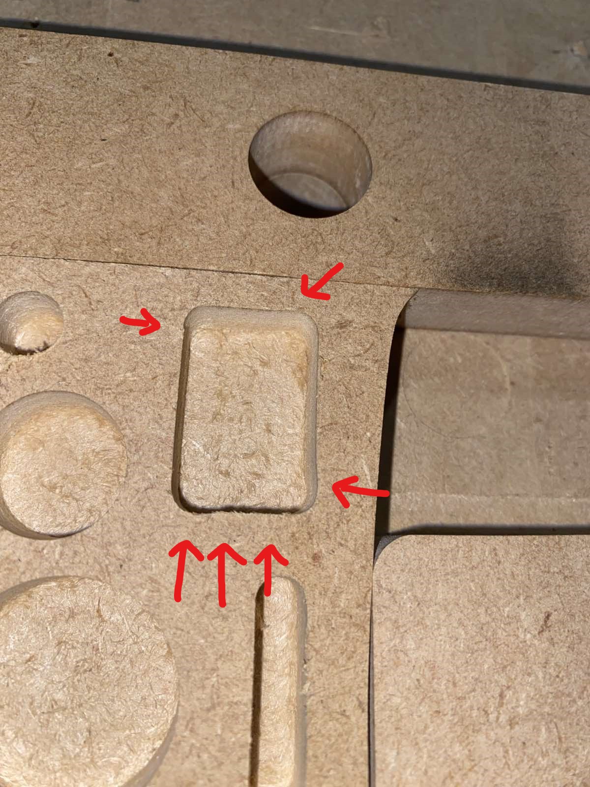
Here’s an image of what I mean. This is a box object, not splines or any curve, so the GCODE should be 100% straight.
These were cut with the Sienci 1/4" DC bit on my MK2 48x30 machine.
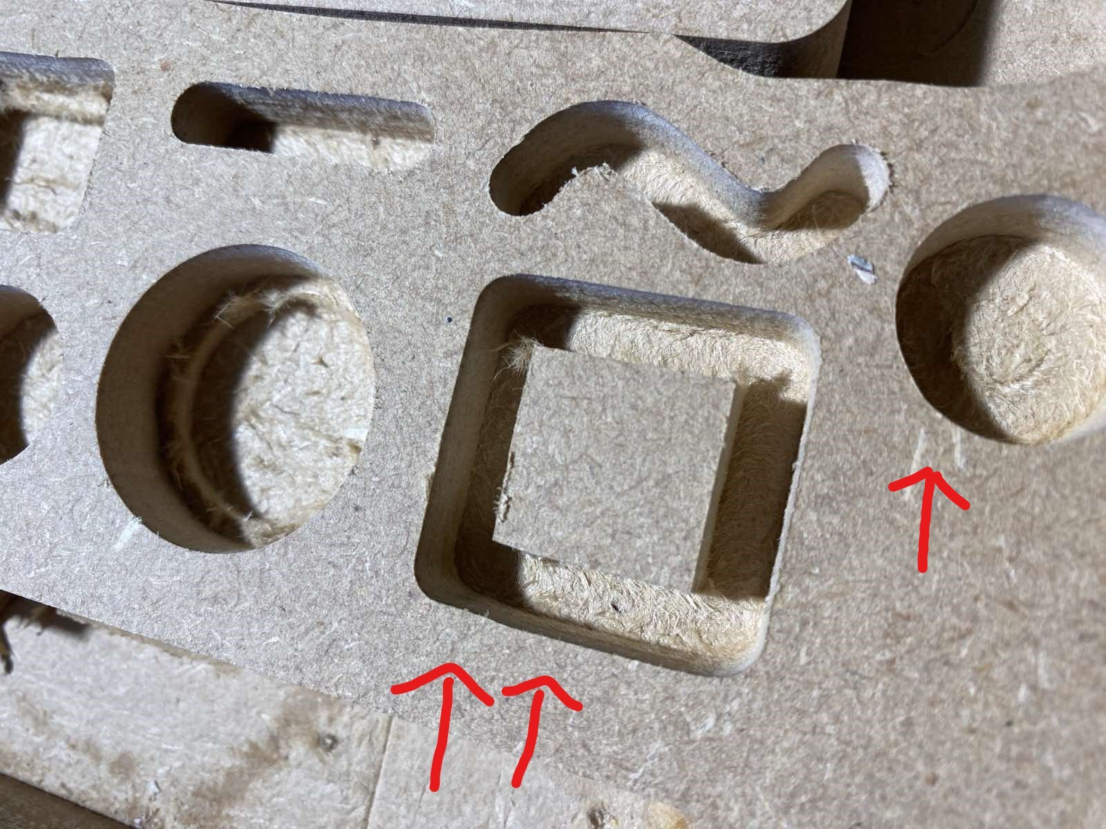
I get the same on circles, particularly in the area where the bit was ramped in to the material.
I do notice that there is a small amount of deflection in the Z gantry. If I grab the body of the router in one hand and the Z servo in the other, I can cause a deflection of the Z plate around the X-axis which results in an approximate 1mm deflection of the bit in the Y plane (could be more - I don’t have the tool to measure this). I’m not sure if this is normal as I never checked this before.
Things I have checked:
X, Y1, Y2, and Z anti-backlash nuts are snug. No play.
Wheels are snug - can barely turn them by hand.
X gantry is totally rigid along the Y gantries - no noticeable play
Z gantry is totally right along the X gantry - no noticeable play
The bolts from the router mount to the linear rails (2 sets of 4) are very tight.
I’ve done the squaring and distance calibration tests and they seem reasonably accurate.
The deflection of the Z gantry seems to be isolated to just the Z gantry itself. i.e. its something to do with its mounting to the X gantry, or within the mechanics of the Z gantry itself as I cannot see any play in the other gantries and I cannot cause the same bit deflection by attempting to twist or move the X gantry by hand - it’s pretty rigid.
Does anyone have any advice on things I could test or check?
Does anyone else see Z gantry deflection when attempting to twist by hand?
I did wonder if the wheels are worn and need replacing. The machine isn’t that old (3 months) and only ran test jobs and this one recent heavy job. As mentioned above, the wheels are very snug and they don’t appear to be moving.
For testing I’ve been using the defaults from the Sienci tool database. In this case, for the 1/4" DC on softwood, it’s set to 4.1mm at 2190mm/min.
I’ll try a few tests at different values to see if there’s any change. I recently cut some 1.5mm inlays into MDF for plexiglass recently, and I vaguely recall they had the same issue, but will double check.
Thanks @Swinly. I am using ramping for this, and the warping effect seems to be worse in the region of where the tool ramped. I’m using CarveCo Maker and its default ramping pattern is a zig-zag.
Regarding lead-ins, In my first image we can see it happens at each change of tool direction so I don’t think I can use lead-ins to treat this particular issue unless there’s a particular trick I’m missing.
With ramping, I switched to using smooth a while back. I can’t remember why I changed it to smooth but it is what I mostly use.
I completely missed your point of it being in multiple spots on the same toolpath. I’m not sure and will have to tap out. Maybe Grant or someone else can help out more.
@RichInNZ I would look into what is causing the deflection that you mention in your first post. That 1mm of deflection could well show up as the defects you are seeing in your work.
Usual preface, I’m with PreciseBits. So while I try to only post general information take everything I say with the understanding that I have a bias.
I’d first test to see if this is actually deflection. There’s a simple test you can run that will let you directly measure the deflection for slotting.
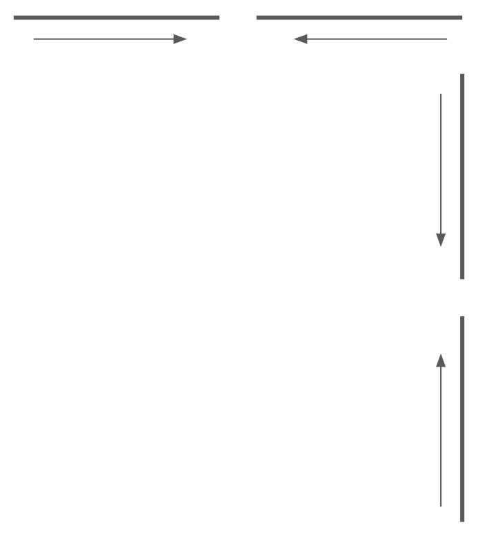
What you want to do is to make 2 cuts with a gap between them cutting in opposite directions (use the same setting and material as your cut). The length of these doesn’t really matter as long as they are long enough to get up to speed. Do this for both the X and Y like below.
Cutting these in 2 different directions changes the side that will deflect. You can then you can measure the difference between the top or bottom edges and divide it by 2 to get your deflection for that axis. Use the middle of the lines as the ends are actually cut slower due to acceleration and deceleration. Some people also like to cut a long continuous line above both the segmented lines to have something to measure against.
If it is deflection and really 1mm that’s quite a bit and I would first guess that there’s something mechanically wrong. Regardless, deflection is caused by an increase in cutting force which is effected by tool geometry (rake, helix, edge radius, etc) and functionally cubic material removed for flute per revolution. So for the same tool geometry any increase in chipload (feed/RPM/flutes), stepover, pass depth, or tool diameter increases the cutting force. Different tools also have different geometries that can effect this quite a bit. As an example a soft media tool will have a high flute rake compared to a “general use” tool and require less cutting force to cut the same chip. Or a higher helix (flute twist) will change the force direction into the Z.
One of the reasons that you will see this in the start of a cut is that you are plunging and effectively pausing (straight plunge) or gradually increasing your pass depth. The straight plunge will deflect and then come to rest leaving a notch. The ramp will slowly take up the force but end up with the same deflection at the end of the ramp.
In some of your other examples like corners is because the machine has to slow down in direction changes. The sharper the angle the more it has to slow down and this slow down changes your feed (chipload) causing less cutting force and therefore less deflection. In the cases of curves this becomes worse if you are cutting lines instead of arcs. Cutting arcs keeps the machine at closer feeds depending on the angles but requires the CAM and controller to both understand them and be able to use them.
Hope that helps. Let me know if there’s something I can expand on or help with.
I did a bit of investigation, but largely came up with a blank. I changed the v-wheels on the Z gantry for a set of new ones to ensure it wasn’t related, but I get much the same result. Obviously in the process I had to disassemble most of the Z gantry, so everything has been re-tightened and cleaned, but none of that seems to have affected the deflection.
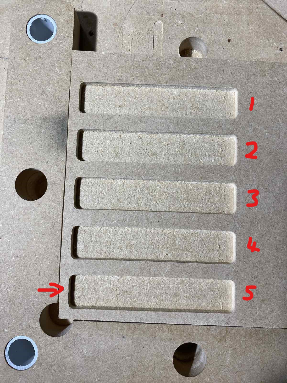
I did run a test with various pass depths. I cut 5 boxes 5mm deep starting at 1mm pass depth increasing to 5mm (top to bottom in the below pic). The 1mm and 2mm pass depths seemed reasonably ok and the warping artefact seems to start around 3mm+. This was using the 1/4" downcut bit at ~14k RPM (2.5 on dial) and ~80ipm using a raster cut (I probably should also try a 90 deg raster to check Y plane deflection).
I am relatively new to CNC so perhaps my inexperience is causing me to push the machine too hard and a slight deflection on a > (0.5 x diameter) deep pass is normal.
I did conclude that I could possibly mitigate the deflection issues without compromising cut speed by accepting this deflection and using a ~1mm final pass offset to clean up the edges (which I gather is probably best practice anyway).
I’ll try that approach and follow up if it’s causing any significant issue.
I can visually see that the whole Z gantry deflects when I put twisting load (around the x-plane) on it by hand. This is observed at the tip of the endmill of around 1mm (guess) at the extreme. As the only mechanical element that is securing the Z gantry to the X are the wheels, I suspect this is possibly down to the stiffness/play tolerances of the wheel bearings themselves. The Z wheels to the X gantry are tight, and the bolts though the wheels are very secure, so it doesn’t appear to be a tightness of fit issue. The X gantry itself is rock solid.
For my sanity, could you comment if a slight deflection in the Z gantry when under load is normal? If not, I’ll try to continue to dig into the cause.
@RichInNZ I can’t speak for Sienci and I don’t know what they consider to be acceptable deflection tolerances. I can say that I cannot detect any deflection in my Mk1 LM. I’m not saying that deflection is 0, just that I cannot detect it.
One thing we have not talked about is the router mount. Since everything else is tight, and since when you grab the router body, you see movement, the last place to look would seem to be the router mount.
I would confirm that the mount itself is tight on the Z gantry plate. Then, ensure that the router itself is not moving in the bracket. In this regard, be sure that the router is not mounted all the way down in the bracket. The router barrel has a “flare” at the very top and you do not want that in the clamp. In fact, depending on the job you are doing, the optimal place to clamp the router is as high up in the clamp as it will go. (I realize that with short bits, this will not work as you will not be able to touch the bit to the spoil board.)
In previous threads on this forum, some engineering members much smarter than me explained what should have been obvious - even to me. The more of the router that is below the clamp, the more leverage forces are brought to bear on the clamp and the gantry. So, they advised to move the router up as far as the project would allow. All that said, if your router is already high up in the clamp, just ignore all this drivel.
Failing that as a solution, I cannot think of anything else to add. As usual @TDA (John’s) input is on point. Your feeds and speeds are very conservative. Perhaps other members can offer other options. You can also open a support ticket with Sienci.
Hey @gwilki. My router is mounted with a few mm of the shaft above the clamp so to avoid the barrel flare. It is all pretty tight - clamp to router is tight, and clamp to Z gantry (4 bolts on backside) are tight. It is difficult to see exactly if there is any deflection in the clamp vs the whole gantry - I’ll see if I can figure a way to check that.
However, I do really like your point about leverage. Considering I have the router mounted at its most extended position, I feel reducing this height would significantly reduce the load on the whole system from the bit. Great suggestion - I’ll give that a try!
It also sounds mechanical to me, too. I didn’t see where you’d checked the anti-backlash blocks. If there’s slop in them, that’ll cause the deflection you’re describing.
I noticed that others mentioned the speed being a factor. I’d try slowing it down even further and see if that makes a difference.
These are pretty small pieces (unless I’m misunderstanding the photos, etc.) which would require the gantry to move quite a bit. If you can feel 1mm of slop in there, to my mind that again points to the anti-backlash blocks. Double check to ensure they’re tight against the mounting area and that they’re adjusted to remove any slop.
I should mention that I also have a Mk1 30X30 and have been CNCing for just a bit over 2 years, so most certainly don’t know everything.
Please let us know who you resolve this, as that’s how we all improve.
Marty from Kingston, ON, Canada
Thanks Marty. I’ll double check them - they do seem to be tricky to get right. Too lose and you get movement, too tight and the steppers jam. And that 12mm one on the Z gantry is a real pain to access.
I’m checking every day to see if the new spring-loaded ABN’s are in stock on the Sienci shop, as they are my first upgrade! Shame they don’t have a 12mm one (yet?) for the Z gantry.
Anyway, the ABN on the Z gantry for the X movement is very solidly bolted to the Z gantry, I checked that when I replaced the wheels. The thumb-screw seems to be at the right tension - but I’ll play a little to see if I can get it tighter without binding. The Y-rail AB nuts appear to similarly well tensioned, but I will double-check the tightness of these nuts to the machine body as I’ve not done that.
I did notice that in the most recent test I posted above, the deflection does appear to be in the left-right direction (as seen on the left side of the boxes) which I agree could be backlash. I also I wasn’t able to replicate any visible twisting deflection of the router/Z gantry in the left-right direction by hand, unlike I can with the up-down direction. Admittedly, the above test cuts were done using a 0-degree raster clear so the router was predominantly moving left-right, so it didn’t really stress the up-down direction of motion.
Thanks for the suggestion. I will definitely update with any findings. If I do draw a blank, I’m somewhat happy to accept a little play anyway and use a cleanup final pass to deal with this issue on any production cuts.
When I tighten the anti-backlash blocks I will loosen the screw until I can feel the play by trying to move the axis back and forth by hand. And I say trying to move because I’m not talking about pushing so hard that the rod turns just wiggling back and forth to feel the ‘slop’. Then tighten till that goes away.
Cool @_Michael, thanks for sharing. I do pretty much the same process too. I use that tell-tale “clunking” noise to measure when it’s tight enough. I’ve also found that tightening them as much as I can by finger results in pretty much the same result also; maybe wiggling the gantry back/forth in the process.
This would follow with deflection but not really give you the where.
Assuming that’s a 2 flute that’s a chipload of only 0.0029". Making A LOT of assumptions (general use geometry, 50% stepover, etc) that only produces a peak force of 1.1lbf.
Raster is about the worst kind of cut you can make for this. It can have more direction changes and depending on how it’s setup and configured can be alternating climb and conventional. If possible I’d switch to maze/offset. Additionally, if you are going for the cleanup/spring pass I would make the roughing pass climb and the finish conventional. This makes it deflect into the pocket on the roughing where you have the most force then cleans up the missed section on the finish.
This all depends on the tool, feed/speed, and machine. In general when supporting any CNC with V-wheels I try to limit the estimated forces to 15-20lbf as they start deflecting a lot after that. Assuming my assumptions are even close to correct you aren’t anywhere close to that force.
Yeah, this is done a lot when going for dimensional accuracy and in the climb then conventional per my above.
Yeah, the same is true for the tool stickout (the amount of tool “sticking out” of the collet). The easiest way to think of this though not technically correct is that your lever is from the tip of the tool to the Z bearing block. The shorter that is the less deflection. So also choke your tool up as far as you can get with smooth shank still in the entire collet length and a gap in the back of the router. Shorter tools and cutting lengths will also help for the same reason.
I’m not very familiar with the type being use here so this could be incorrect. Generally though backlash gets taken up in error in direction changes. So it should show up with a simple test of moving in one direction say 6" and then going back to see if it’s in the same position. Using this thread as an example if we say it’s loaded going into the X zero start then we move 6" we will get 6" of travel. But when moving back it will pickup the presumed 1mm of slop in the 6" move back leaving it 1mm short of the starting position.
Are you saying that it is incorrect to have the bit all the way into the router? Still clamping on the smooth part but bottomed out so to speak. I was not aware of that and I don’t think I usually bottom them out but I just did to take some measurements for another post.
I would appreciate a quick reason as to why it’s bad, I like to learn things, especially if I’m doing something that could be bad for me or my machine.
When you tighten the nut the collet will first grip the shank preventing bit movement. Then as you continue to tighten the nut it forces the tool “up” with the nut and collet. If the tool is bottomed out this ends up either cutting into the back of the router/spindle or more commonly keeping the collet from properly seating causing runout. In worse cases it can damage the bit, collet, or nut. So it’s best practice to leave a gap to allow the tool to move up while tightening the collet.