Sorry for the delay. Weekend and Mondays…
You can run a straight slotting deflection test using the method I posted here: Non-straight lines, possible Z gantry deflection - #9 by TDA
I do have another much more complicated version of this that tests for deflection with less than 100% stepover. Let me know if you want it.
Another quick way to check this would be to run a second pass. It’s not great for the tool as it won’t (or at least shouldn’t) be cutting much. But if running a second pass removes the steps or remaining material than the deflection is at least part of the issue.
I wouldn’t say this rules out warping. If you want an easy real world way of testing this use something with no grain like MDF or a plastic. While those can still warp they are not for the same reasons or in the same ways.
The first 2 things I would guess is out of tram or deflection can basically cause the same thing (tool/machine bends so the tip is no longer “flat”).
Going through the info I didn’t get to address last time.
That compression cutter no matter what is going to deflect, potentially a lot. It has a very long cutting length and even greater stickout due to being a ground down on a 1/4" shank. To demonstrate what I mean I’m going to be using a tool call Millalyzer. To be clear this is just giving it’s best guess of forces and their effect. It doesn’t account for everything and makes some assumptions. Additionally, I have to make some assumptions as there’s only so much of the tool geometry that I can get from a picture of a tool. For my assumptions I’m going to assume a “generic” geometry and I’m modeling an extremely rigid system to try and show only the tool’s effects. I’m also using MDF for these as it’s the softest material I can model for this.
Let’s start with the 1/4" tool to show something in the more normal range. Here’s what that looks like with your listed feed, speed, and stepover. I’ll be using 1.25" stickout for both this and the 1/8" compression tool.
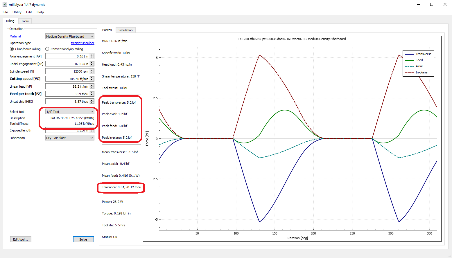
So in this fist one we can see the estimated tool stiffness is 11.95lb/thou. Meaning that it takes that much force to move it 0.001". We can also see the estimated forces for those cut settings with a peaks being 5.2 pounds resulting in the tool in a single rotation moving 0.12 thou off path.
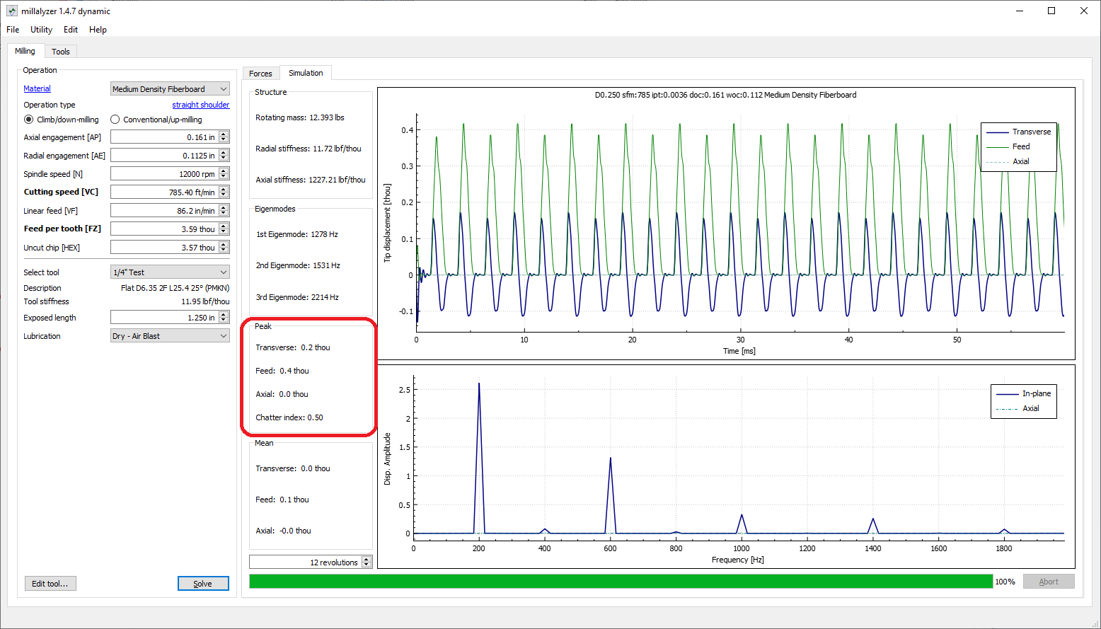
This is what it looks like trying to account for the tool having to return and cut in the previous error. You can see the waveform at the top which is the amount the tip is moving off path and the peak results in the red box . 0.4 thou feed (cut direction), 0.2 thou transverse (perpendicular to the cut direction).
Now let’s look at the very long 1/8" tool. Again using the listed settings from your screen shot.

The force required to move this tool 0.001" is only 0.95lb. This cut produces a peak force of 2.3lb and the estimate for a single rotation off path error is 0.84 thou.
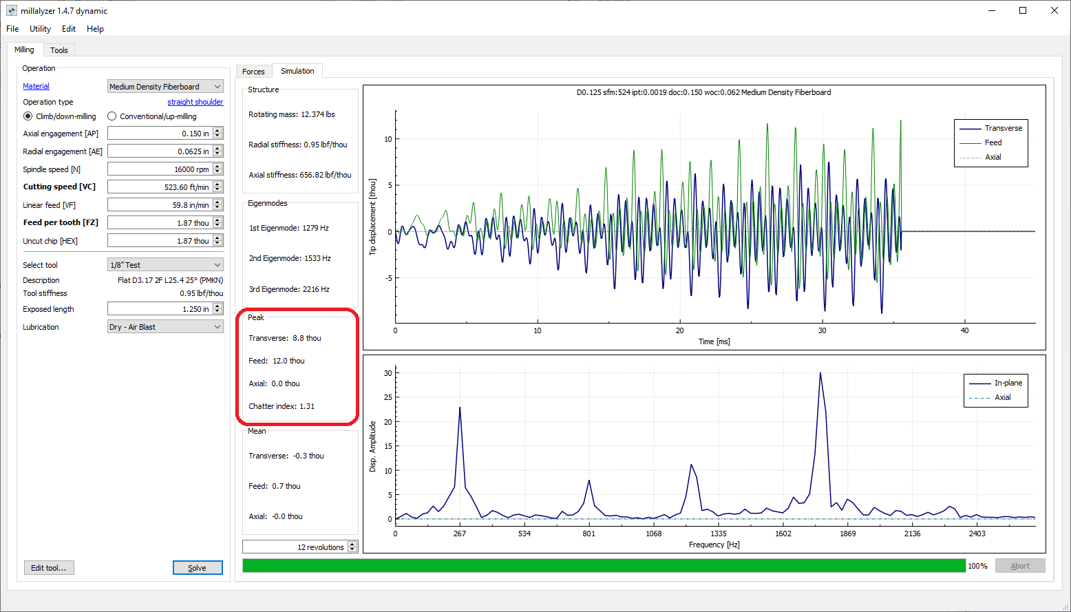
Here’s where we get into the real problem. As you can see this error accumulates to the point were the program gives up calculating the error as it exceeds 10% of the tool diameter in less than 12 rotations. This means that the tool is going to move more than 10% of it’s diameter off path.
Again, this doesn’t model everything. It assumes a certain carbide grade, I’m assuming geometry, and there are many geometry and material factors that are not accounted for in the program. That being said it shows a like for like massive difference in the tooling and a lot of errors can crop up if a tool is bending even close to that much in it’s cut.
There an saying I like to use. Every part of a tool will be used. Either for or against you. So don’t buy any feature you aren’t going to use (length of cut, flutes, etc.).
To be clear. I’m not saying this is a bad tool. I don’t know enough about it nor even if I did would I comment on that. It’s just not a good fit for this application. Or at least not without finishing passes.
So all that’s to say I’m not sure that that tool is causing this issue but it’s adding a huge variable. If you need the 1/8" tooling get something that has a much shorter cutting length and that you can choke up further into your collet. Even a 0.5" cutting length 0.8" stickout will produce much closer numbers to the 1/4" tool. Again a simple test to see if this is part or all of the issue is to recut the toolpaths (preferably immediately after the first pass without changing mounting or zeros).
Hope that actually helps and isn’t a just a bunch of techno babble. Probably could have said it a lot more simply but wanted to show the why and by how much difference there is. Let me know if there’s something I can help with.