Yes, that would work too.
My lead screws are only 100cm long where as the originals are 101cm if I remember right. That would have given me the needed length.
A narrower collar would have forced me to use an M3 for locking…eh, not much thread holding on M3 in aluminum. Brass would be better for going small.
How does one make one of these?
I turned them up on a lathe. I think I just made a hand sketch, but if you’re interested, I could model it in 360. You could easily get your dimensions or change it, to fit your needs.
Hansi
Just remembered, that the simplest would be, to take a motor coupling and just Mill/grind/cut off the two dogs. Turn down a step on the one face, and there you have it.
That’s where I got the idea from. I just didn’t have any spare couplings.
Note: just make sure the diameter matches your design and that the clamping screw doesn’t catch the printed leg.
Hansi
I don’t have a lathe, so that’s a no-go for me 
I guess instead of turning a step, you could put a thin washer onto the shaft first, up against the bearing. The idea is to have the coupling/collar only push against the inner race of the bearing.
I would still try to belt sand or even hack saw the two drive dogs off the back… That could lead to a nasty situation if something would get caught on them.
Hansi
(I was referring to the custom eccentric nut actually. Sorry for the confusion)
Ah, no problem.
Sienci sells them, if you are in North America.
https://sienci.com/product/m5-threaded-eccentric-nut/
I didn’t find any long sleeved version anywhere else, so that’s why I made mine.
Yes, that’s lathe work.
Hansi
If short sleeved version suits your build, you can find them on AliExpress under search
“openbuilds eccentric”
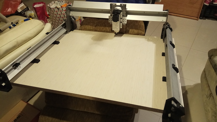
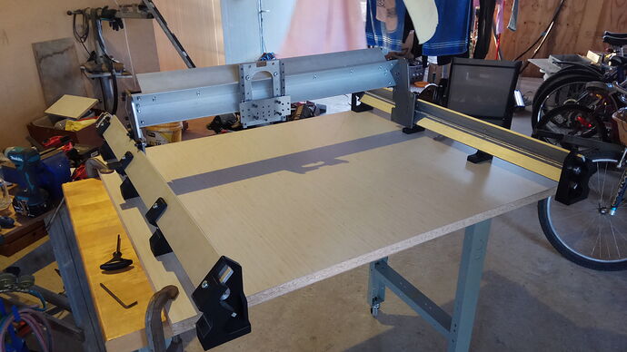
Corona time, helped me get ahead on a few fronts of this project…
Just a temporary base that you see there.
I still have lots of work… But rewarding to see it this far.
You are making great progress, congrats.
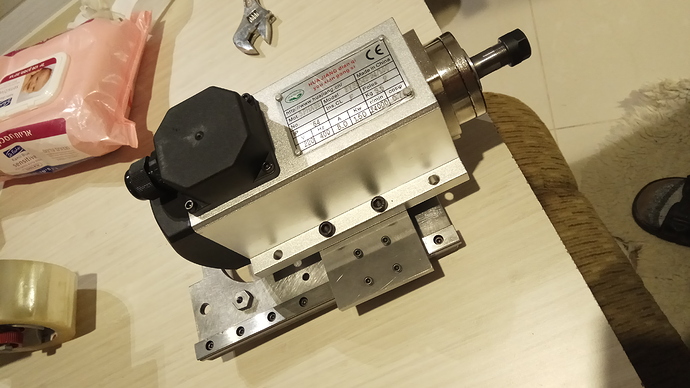
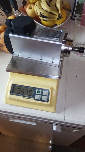
I see one thing in your pics that will attract a lot of attention - a 1500W air cooled spindle. I am very interested to hear how you make out with that. I really like the Makita router, but drilling at 10,000 RPM is risky at best, so the lower speeds and lower noise are really attractive.
Thanks.
Thanks Bill!
Yes, I like the spindle too, but I did not expect or think about the weight, when I ordered it.
Probably not ideal for fast peck cycles but if one keeps the Z travel speed in mind, I think it will be useable.
Open for suggestions though.
That’s what I have… So I’ll go with it.
Just to note:
The round version of air cooled spindle would probably be a better option for directly replacing the Makita.
With this square frame I have to add some parallels under it, so that the motor clears the Z axis top plate.
Hansi, I’ve enjoyed this thread. I like your can-do attitude.
If the Z axis performance is an issue, you could move to a NEMA 23 motor with a higher torque rating. The motor Sienci provides is rated at 12.6 kgf/cm (1.24 Nm) (see http://ldomotors.com/products/show/57mm-hybrid-stepper-series, model LDO-57STH562804AC). You can get NEMA 23 motors in up to 3Nm torque ratings, which would certainly overcome the added weight of the spindle (approx 1.7 kg extra).
I suspect that flex in the gantry would be more an issue than the motor torque, though, when doing rapid Z movements. Have you considered epoxying the two aluminum angle irons together to increase the rigidity of the gantry?
Thanks Iguana:
Actually never thought about either of those solutions. Great ideas!
Ya, a high torque 23 should solve that…my drivers are good for 4A I think. I did think about a different pulley ratio.
Wow. Never crossed my mind, to use epoxy on those aluminum angle irons. Would adding a lower row of cap screws help in a similar way?
Hansi
