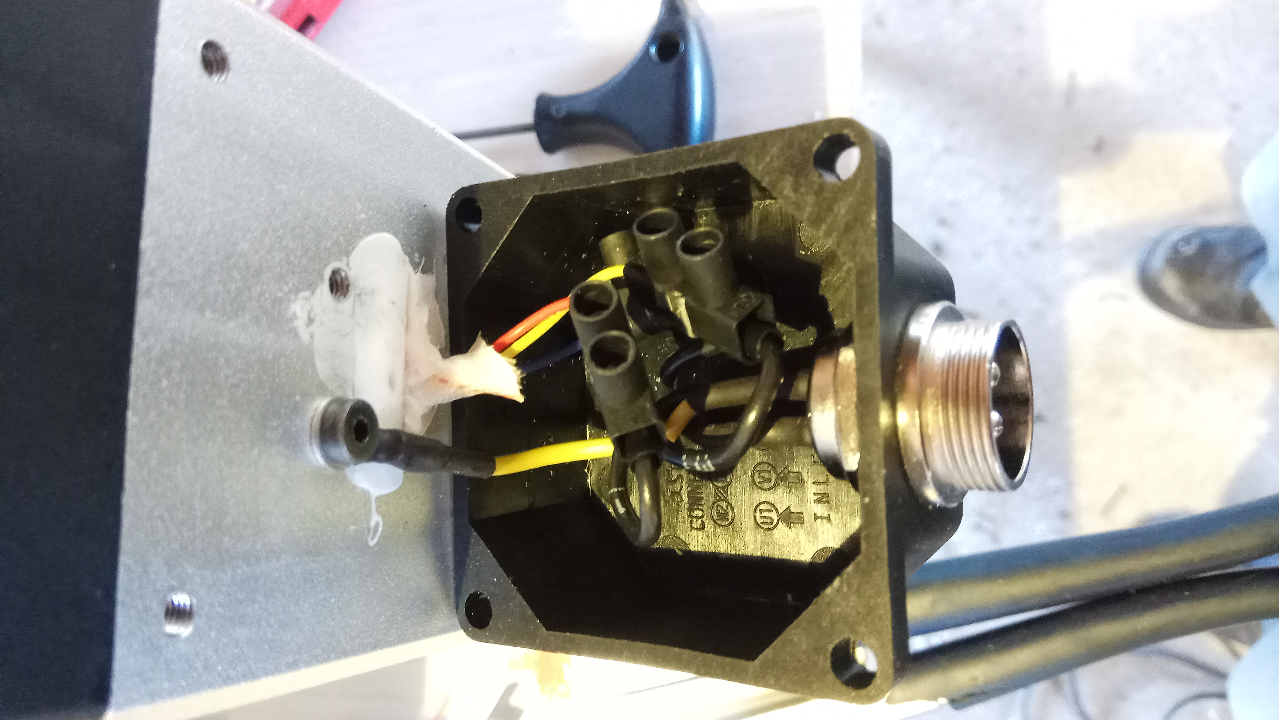
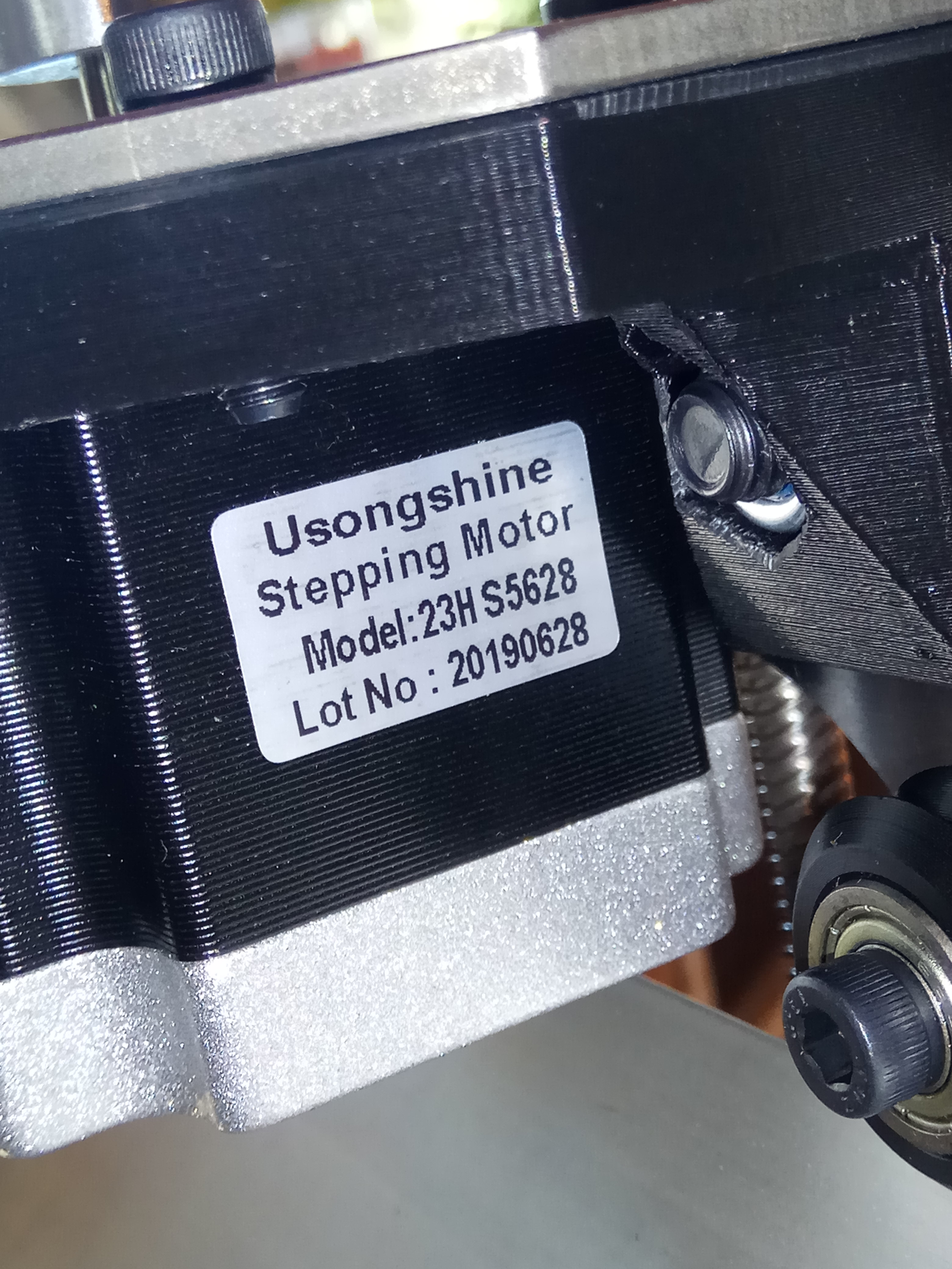
Motors are pretty much the same.
My controller is the DDCSv2.
I added a simple Y-axis drag chain support. The drag chain that I ended up getting, has a 180° swivel end link, so the chain would just droop down, behind the support. It’s hard to figure out all those details when you order from AliExpress… But that’s part of scratch building.
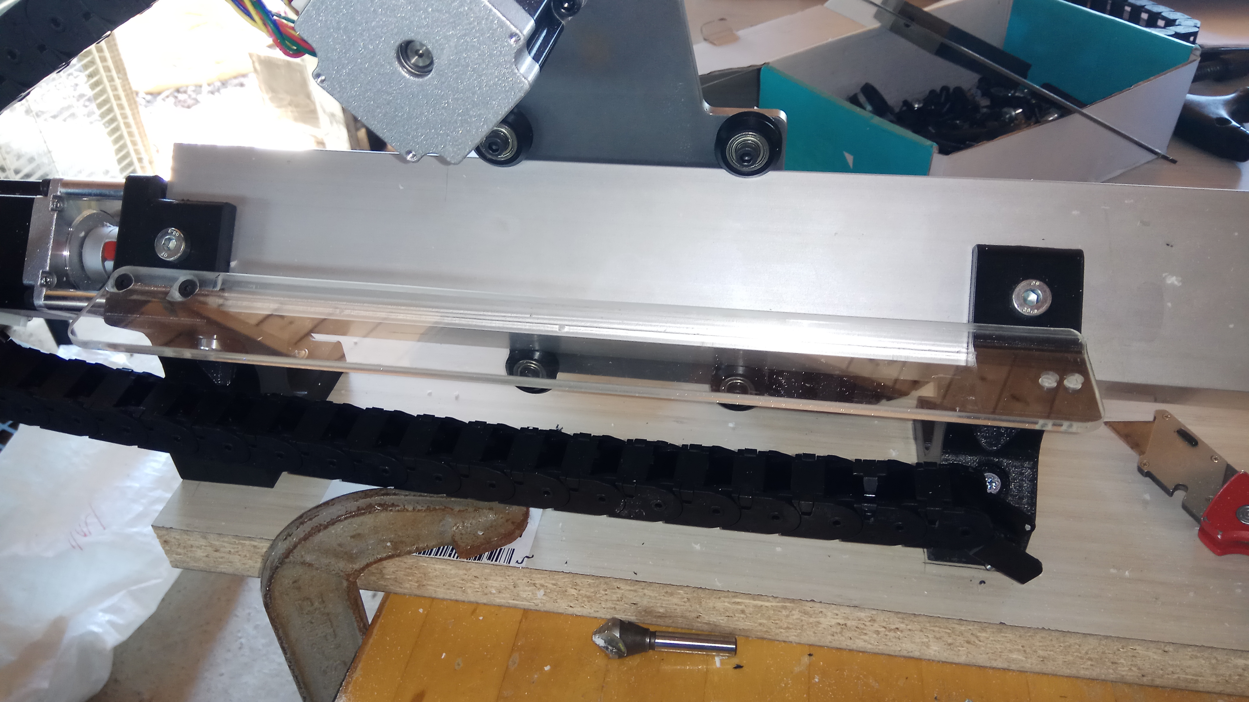
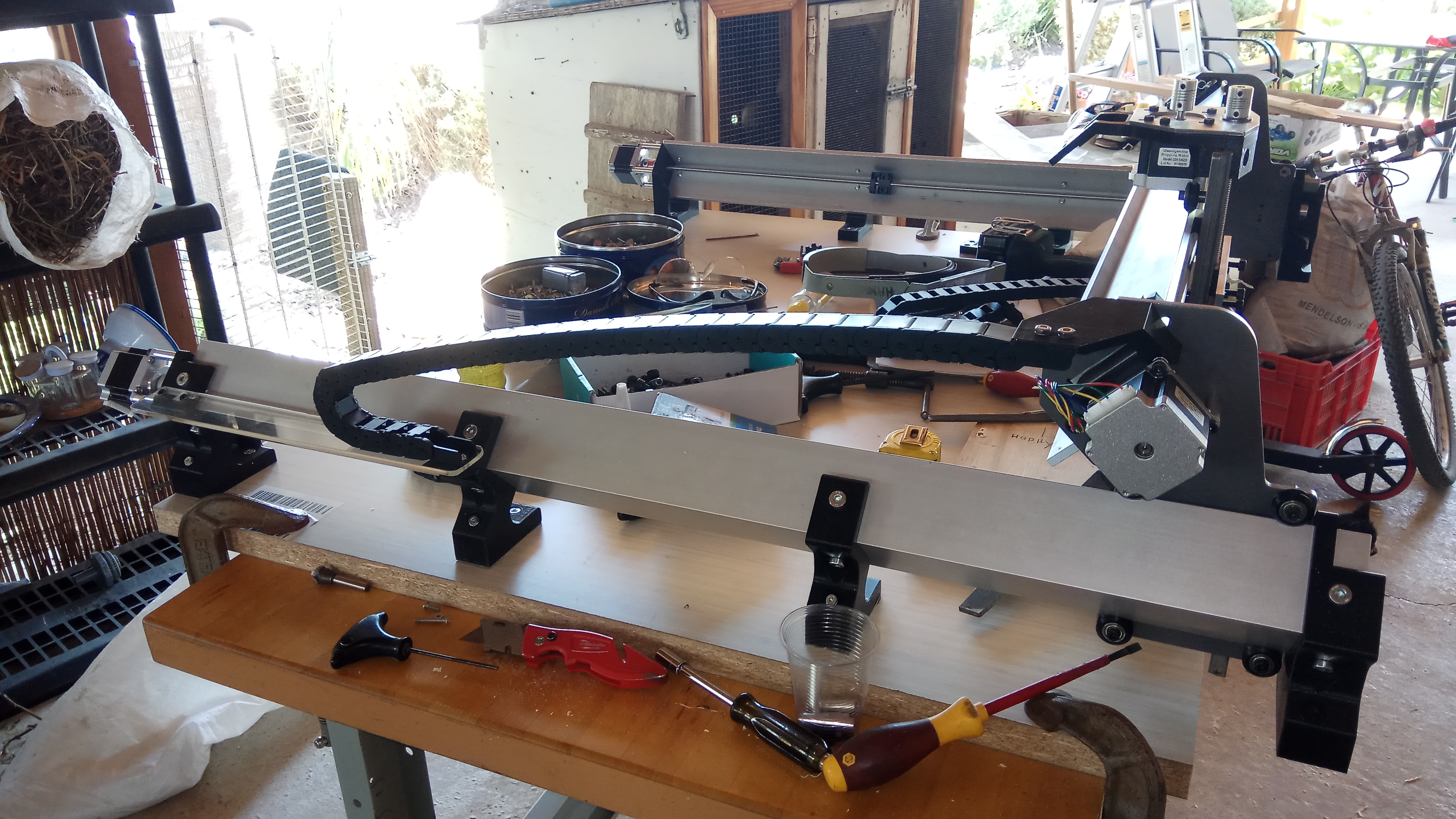
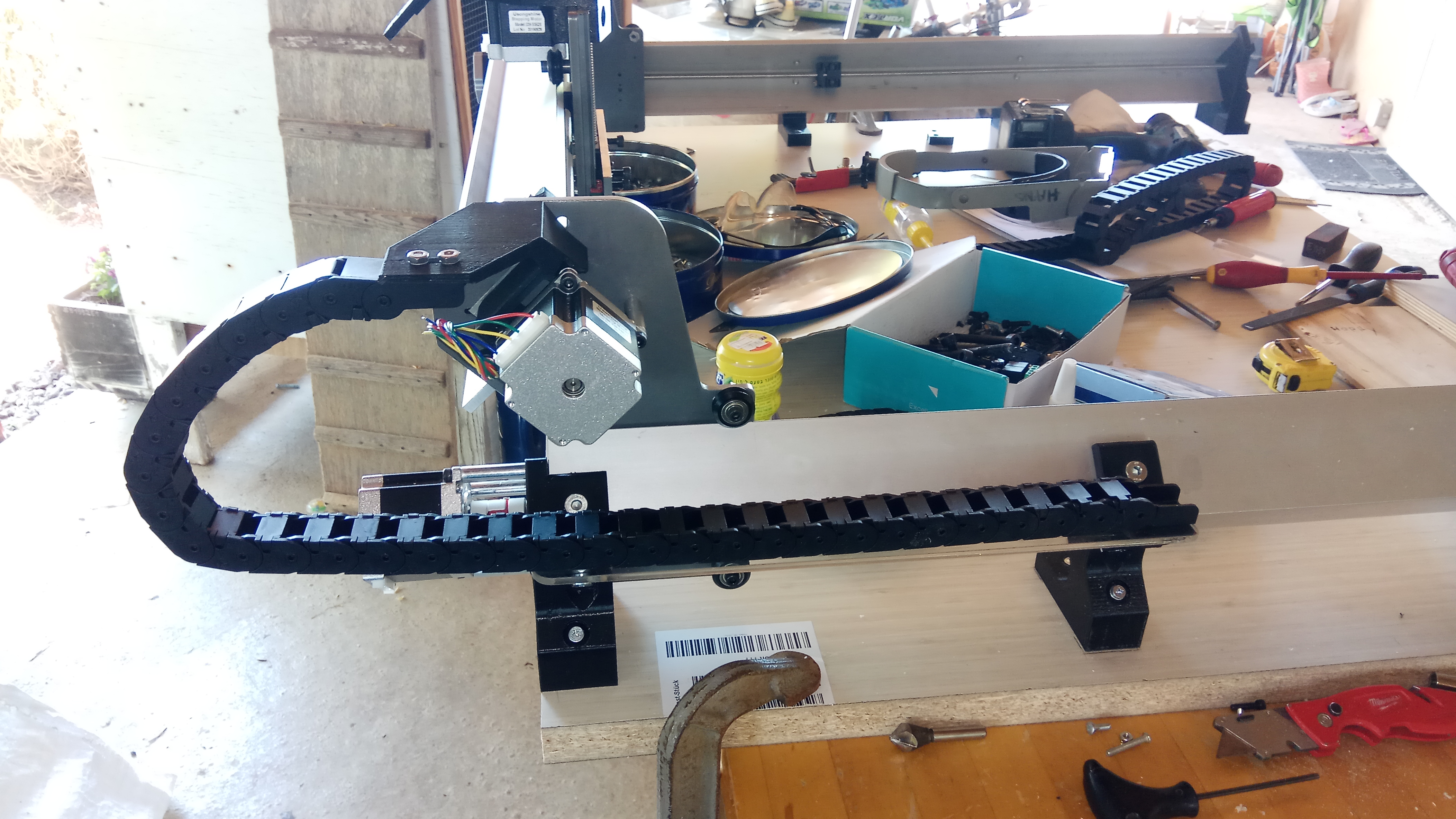
I did shorten up this chain by 5 links, after I took the picture
Waiting on more supplies… Aviation connectors, cables, ds37 components, 2GT pulleys, switches etc. from China.
Stuff is coming. Just a little spread out.
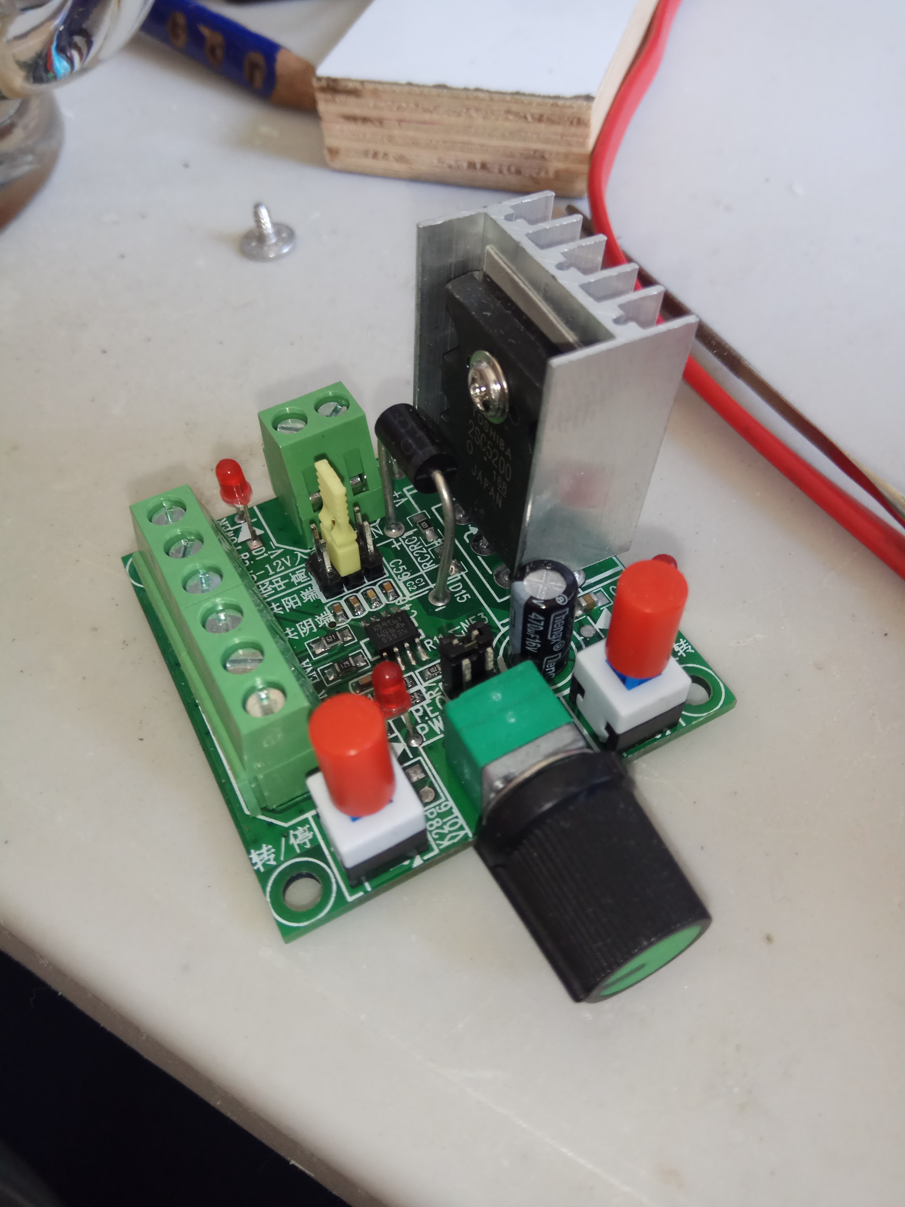
I may just test out my axis’s with this cute PWM signal generator board I got.
Let’s see…
@Hansi I bought the 30x30 model and I am now looking to get it smaller (Y-axis). I could cut the profile or get another one instead and use the old one if I have more space. I can only get 70x70x7 profiles and was wondering if you shared your reworked brackets somewhere.
Hi Gert:
I would gladly share… Just need to figure out how to do it  .
What’s the best way and best format?
I did all the mods on Fusion, so there would be all kinds of export options.
Or just the STL’s?
Don’t forget the V-wheel spacing on the main gantry changes, because of the larger aluminum angle.
Hansi
Gert:
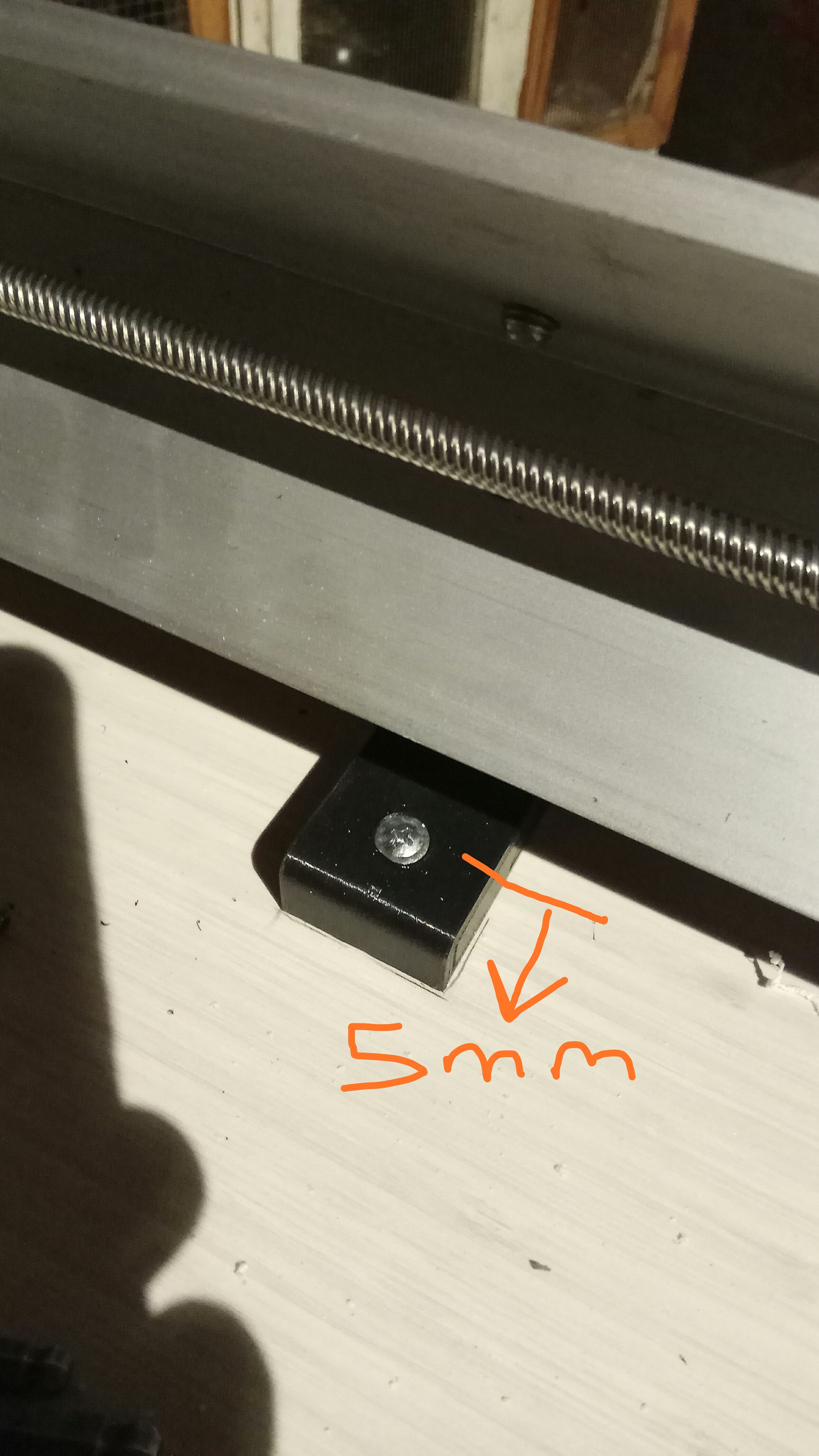
I would change one thing… Move the vertical screw down hole, in the middle leg supports, 5 mm outwards. The angle iron was a little in the way of getting the screw down.
@ALL:
I’m trying to compare the cutter deflection of my build, to that of the original LM with Makita.
Maybe someone has established some values of the different variables:
-Distance from center of X-axis to force exertion point
-amount of force applied
-distance from X-axis lead screw to indicator
-etc.
Hopefully I’m understandable.
Hansi
Video to show kinda what I’m referring to
Hansi, I can offer up this video I made late last year. Let me know if that provides the information you need:
Yes, exactly! Thanks Chris.
I remembered now that I had watched that back in the beginning while I was researching… I guess I’m getting older.
The following are STL’s for the components I printed, in order to use 70mmx70mmx7mm ALUMINUM ANGLE
1 Like
Hi Gert:
Please check out the above links, and let me know if they work. I printed all the parts laying flat on their backs. You will have to re-orientate them when you bring them into your slicer.
Don’t forget to modify your steel Y-axis gantry plates, so that they will handle the larger opening (hypotenuse) of the aluminum angle.
Thanks for the files, I was able to download them. Looking into it and 70x70 might be a lot more work since the gantry also needs adjustment.
Yes, that’s right.
Maybe you can order the right stock?
Be very careful if you mill any stock down to size… There’s surface tension holding those profiles straight, and will need to be milled off equally in every dimension.
Best of success,
Hansi
The wiring harness that these motors come with are pretty fine…like 24-26 AWG compared to my 20 AWG that I’m trying to use.
Other people even use 18AWG
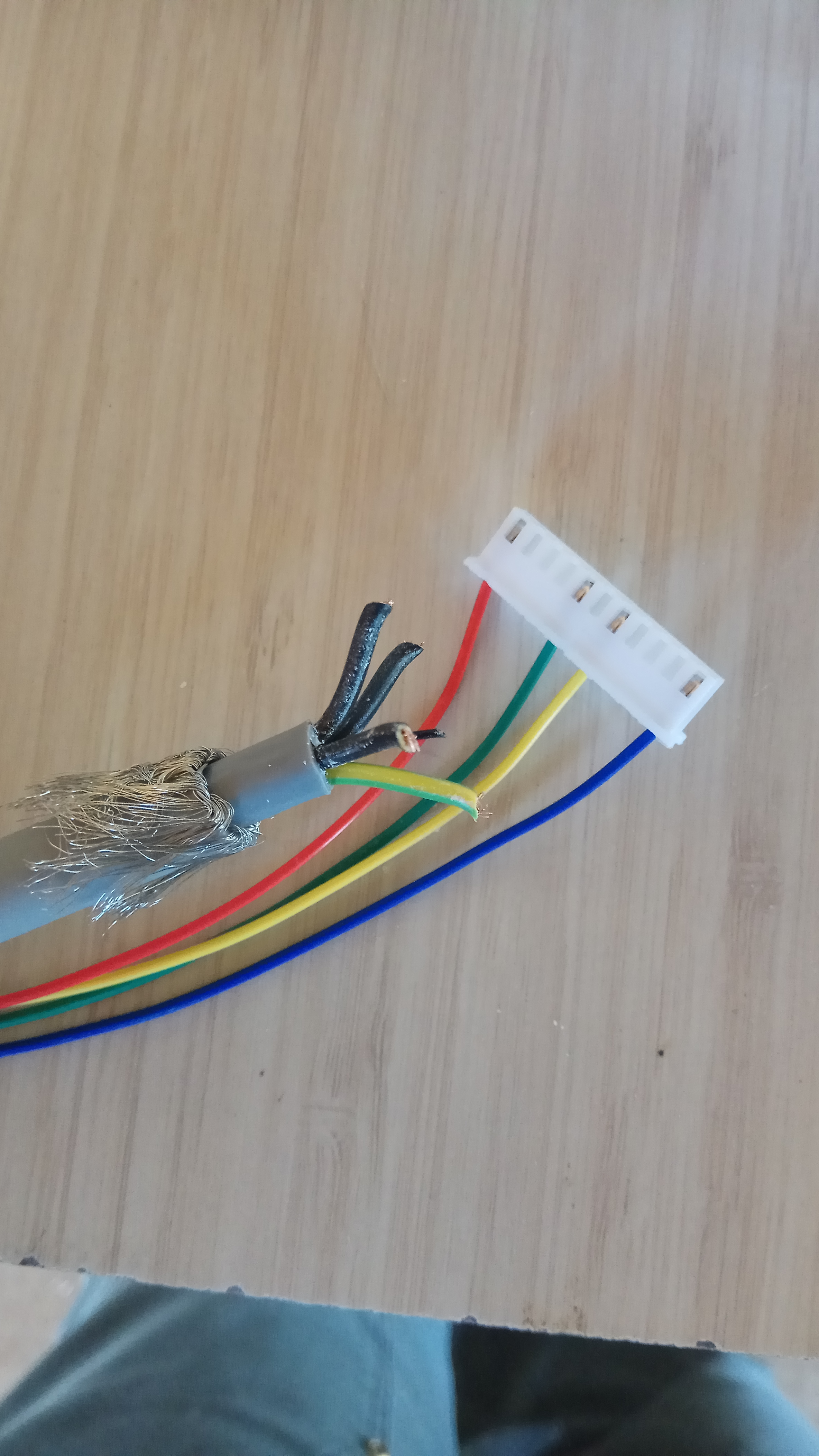
Other people even use 18AWG
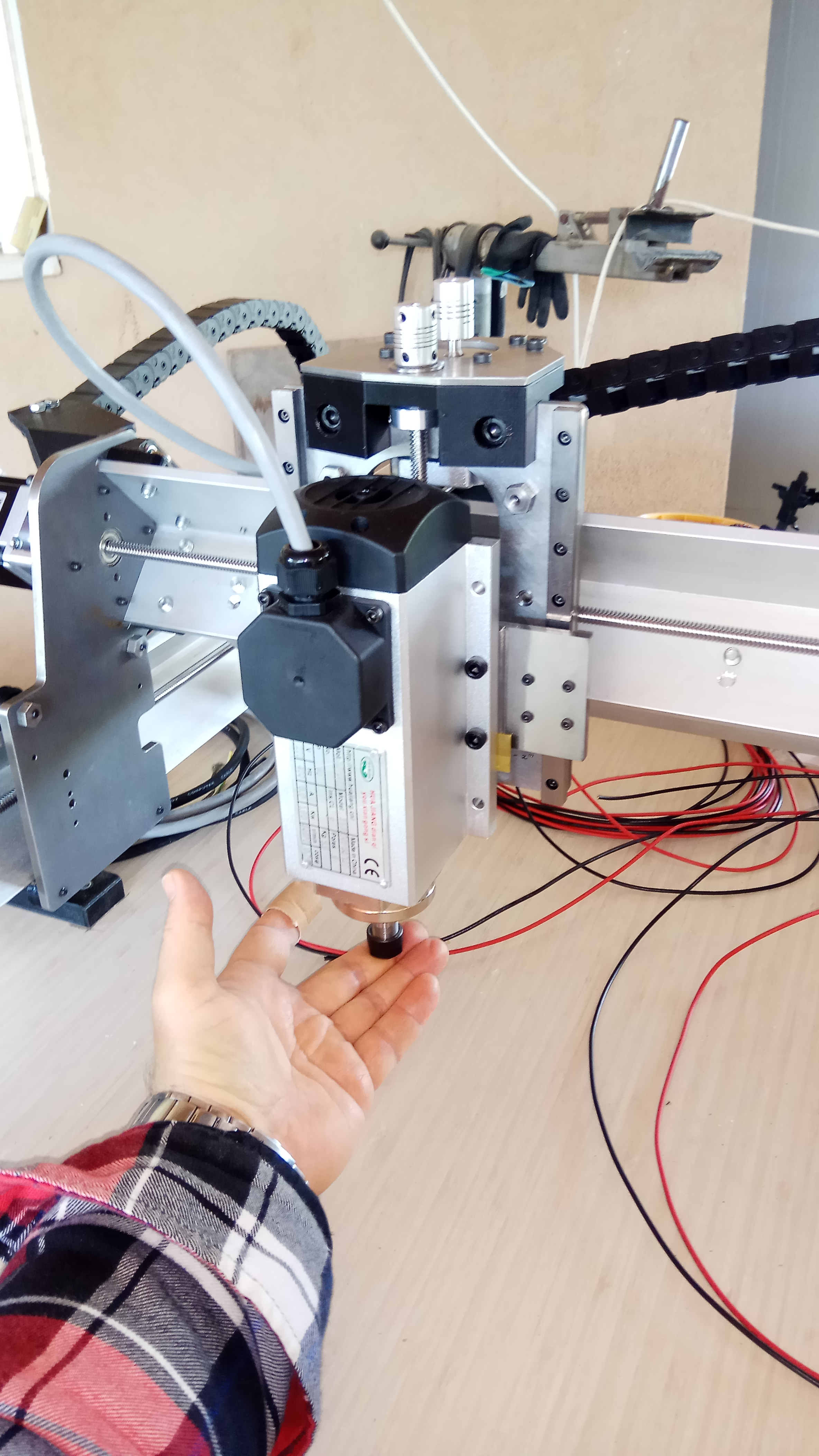
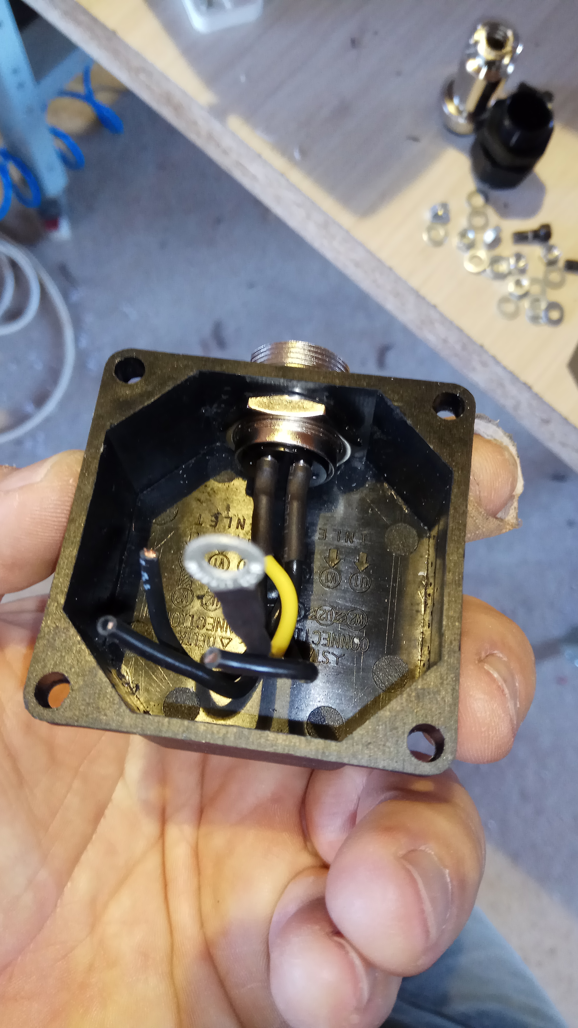
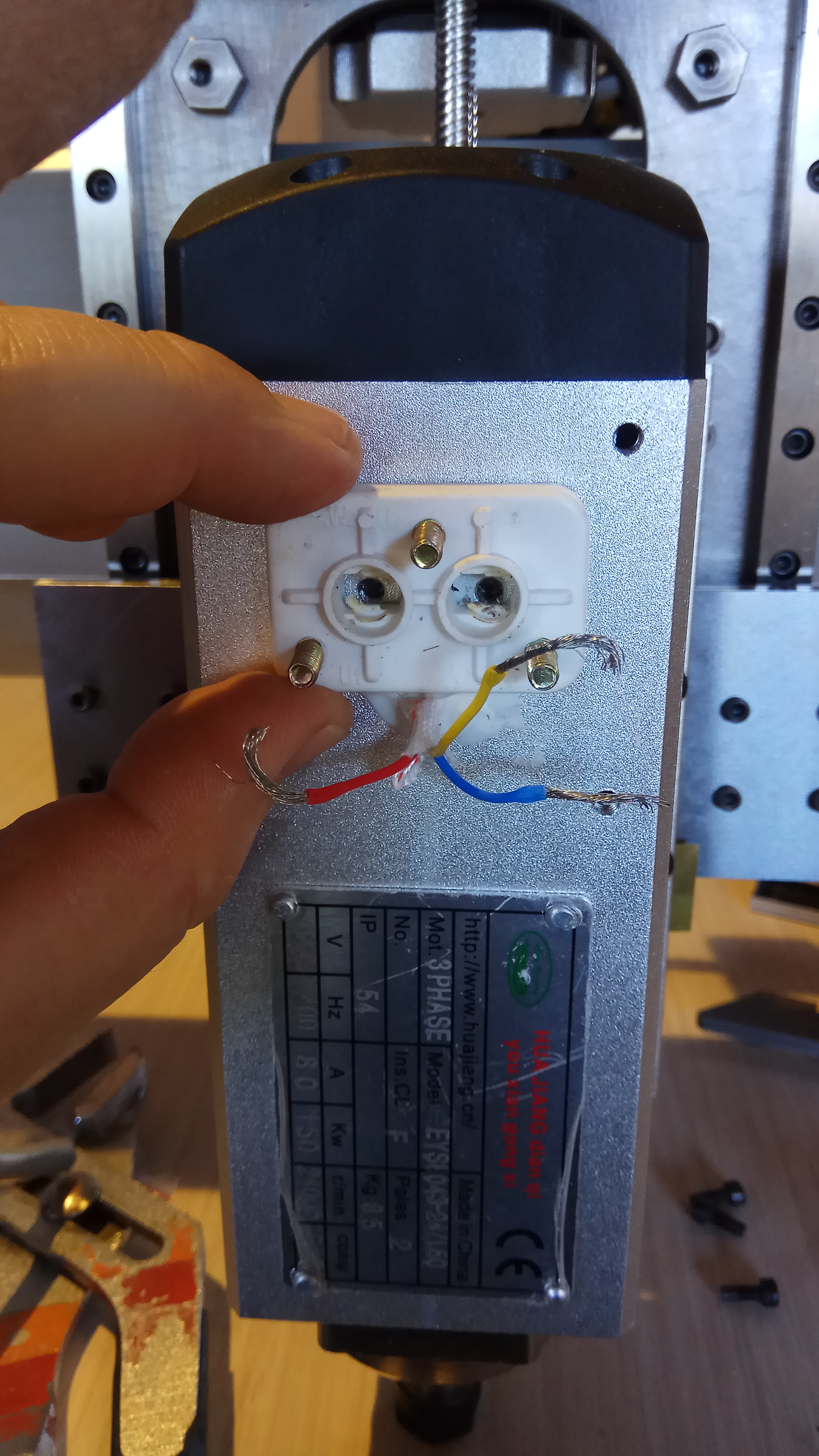
Take out the stock wire mount and use one of its mounting holes to attach a ground wire. Some people trust that the mechanical connection from the motor to the CNC chassis, is good enough, but in our case we have all kinds of plastic parts in between.