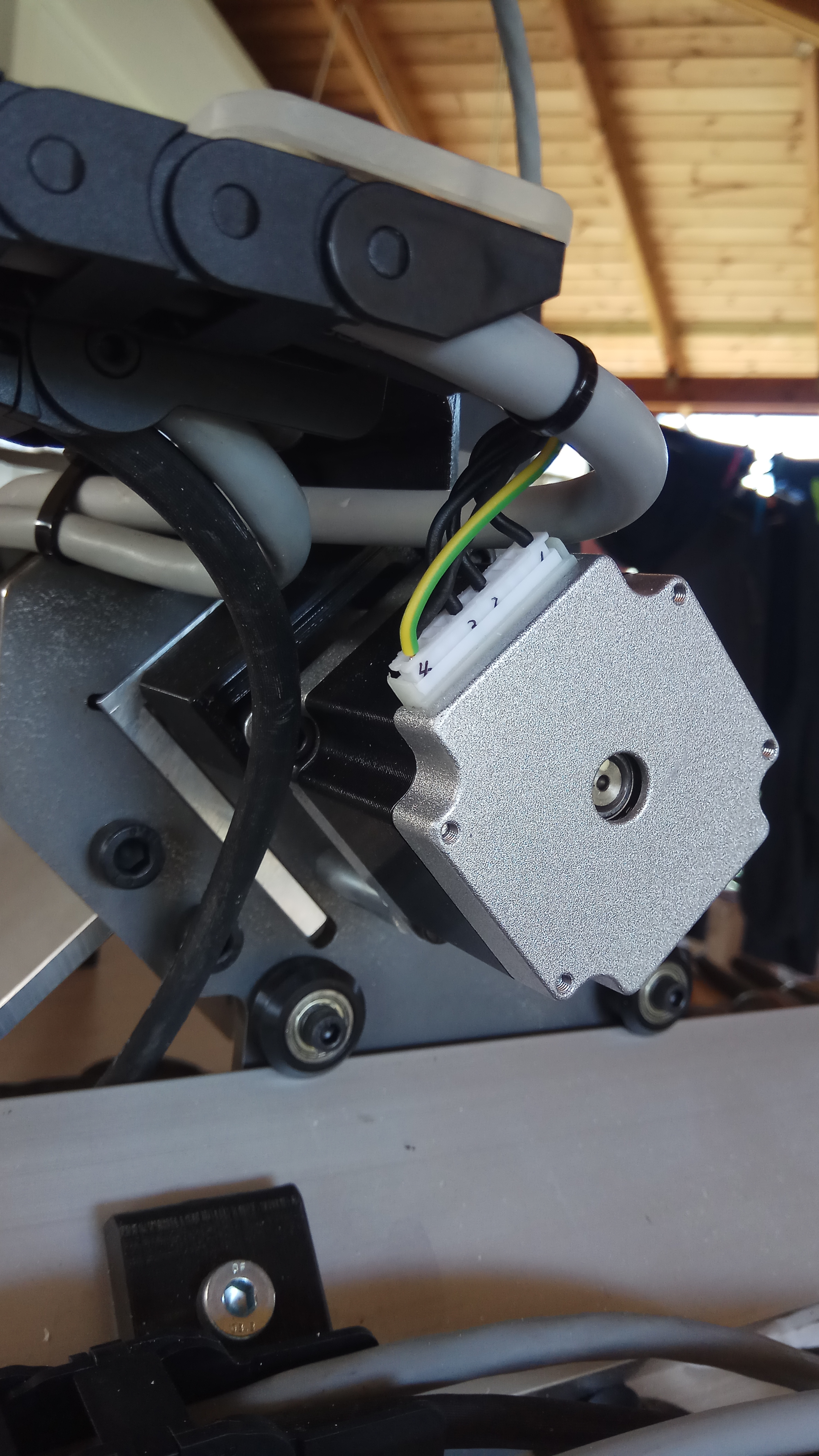
Take out the stock wire mount and use one of its mounting holes to attach a ground wire. Some people trust that the mechanical connection from the motor to the CNC chassis, is good enough, but in our case we have all kinds of plastic parts in between.
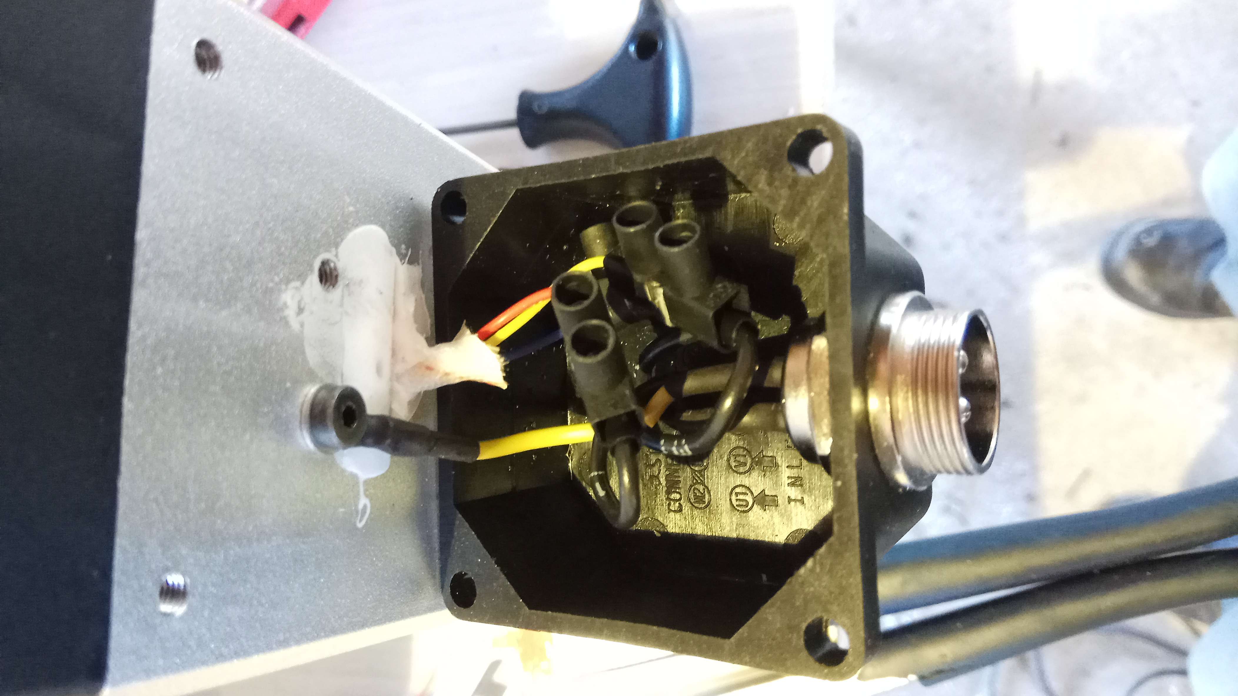
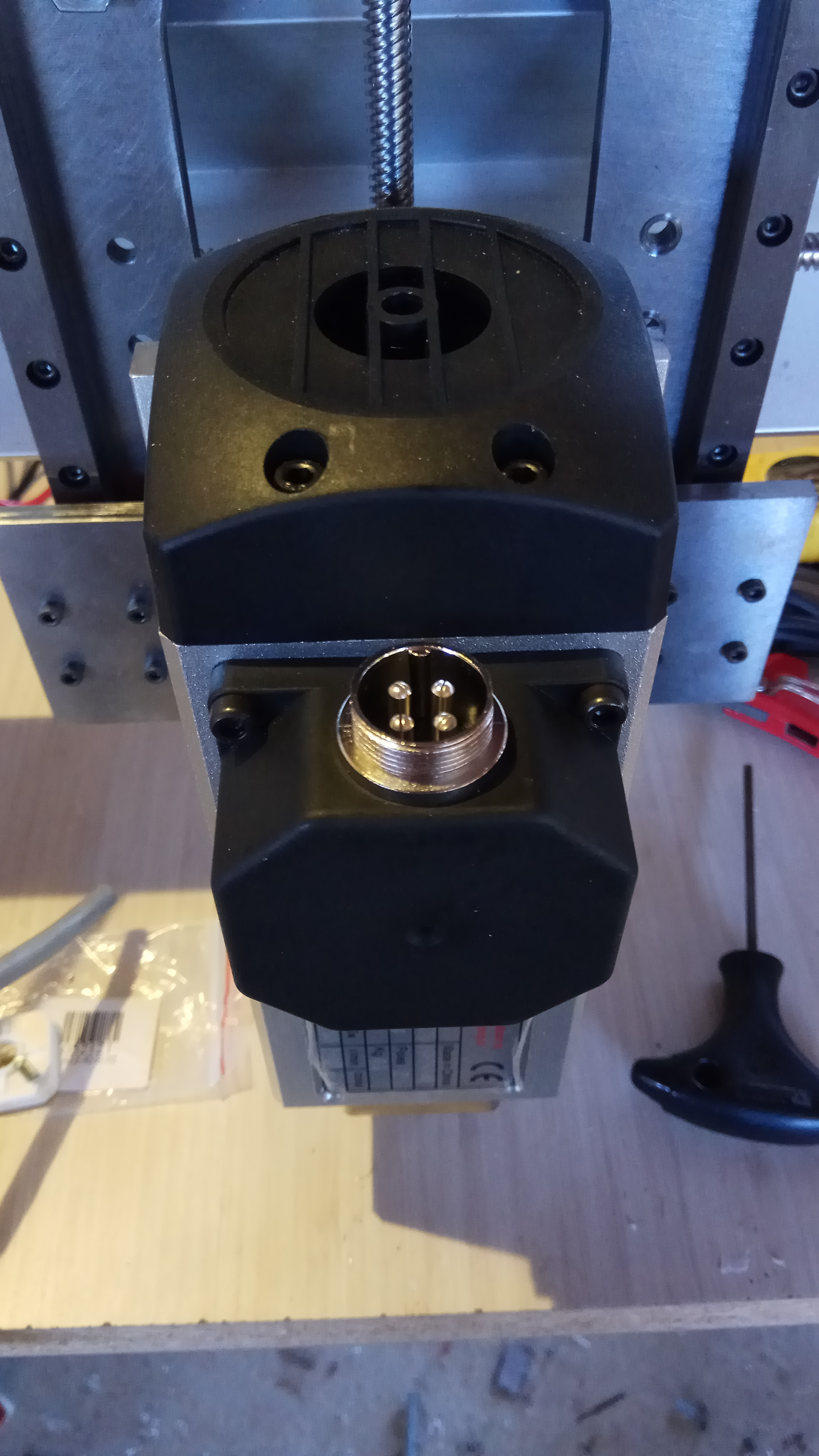
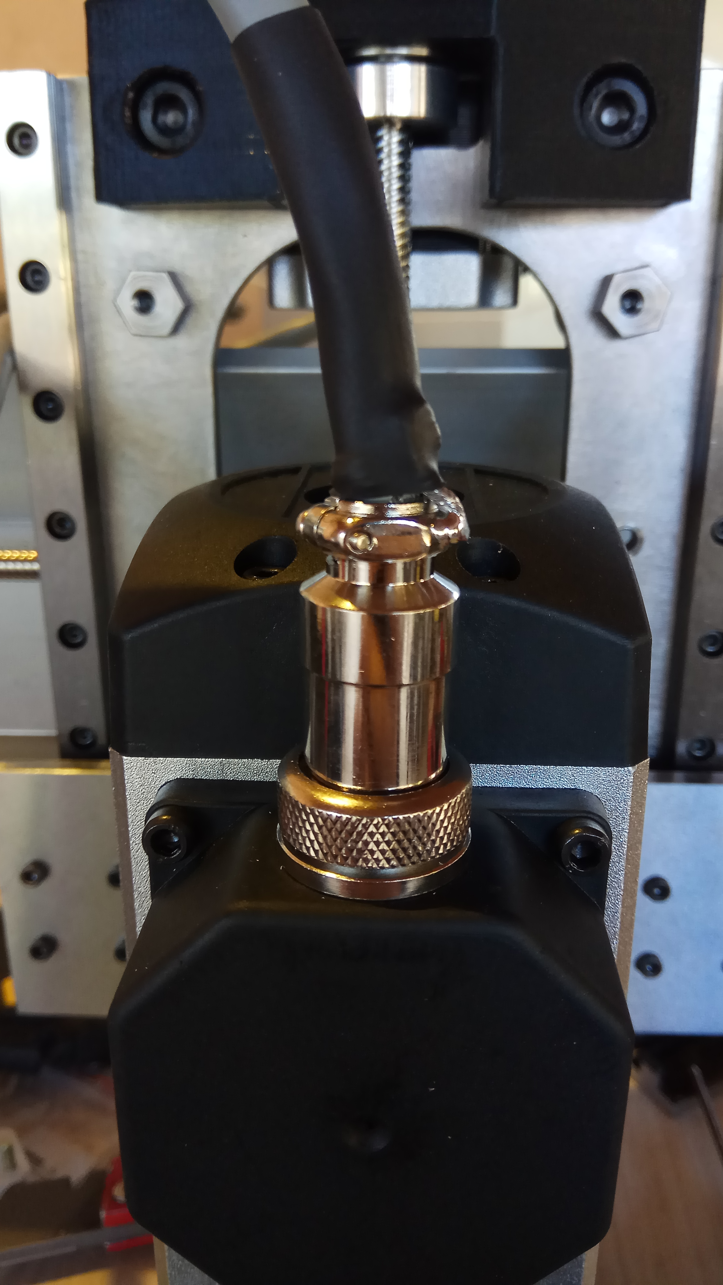
Actually really nice plugs, and unbelievably DIRT CHEAP!
I’m familiar with Amphenol from industry, which these obviously aren’t, but well worth their couple bucks.
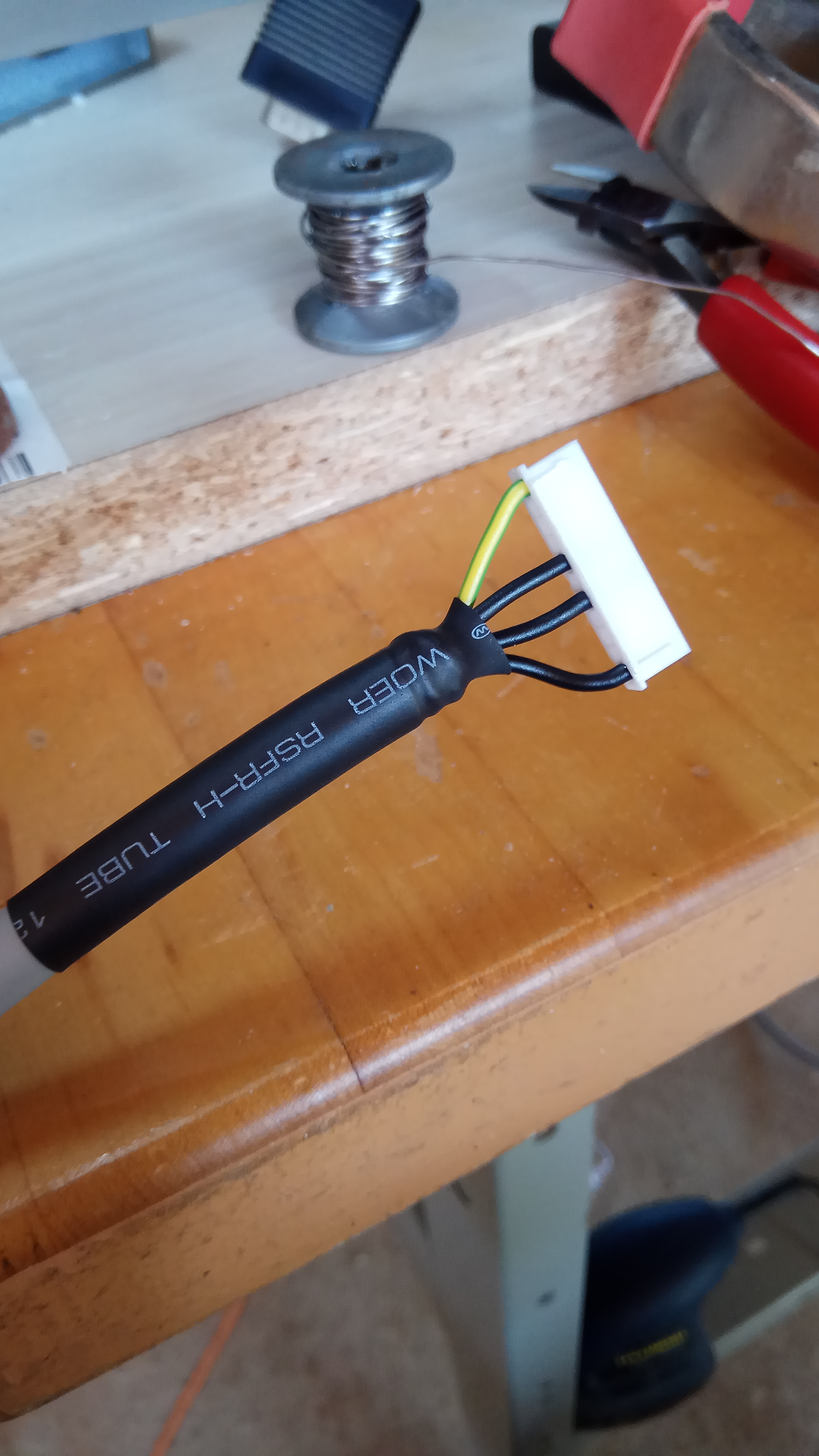
I should have ordered 5 pin, like I did on the steppers…I forgot about the shield, and brought it out to the plug housing.
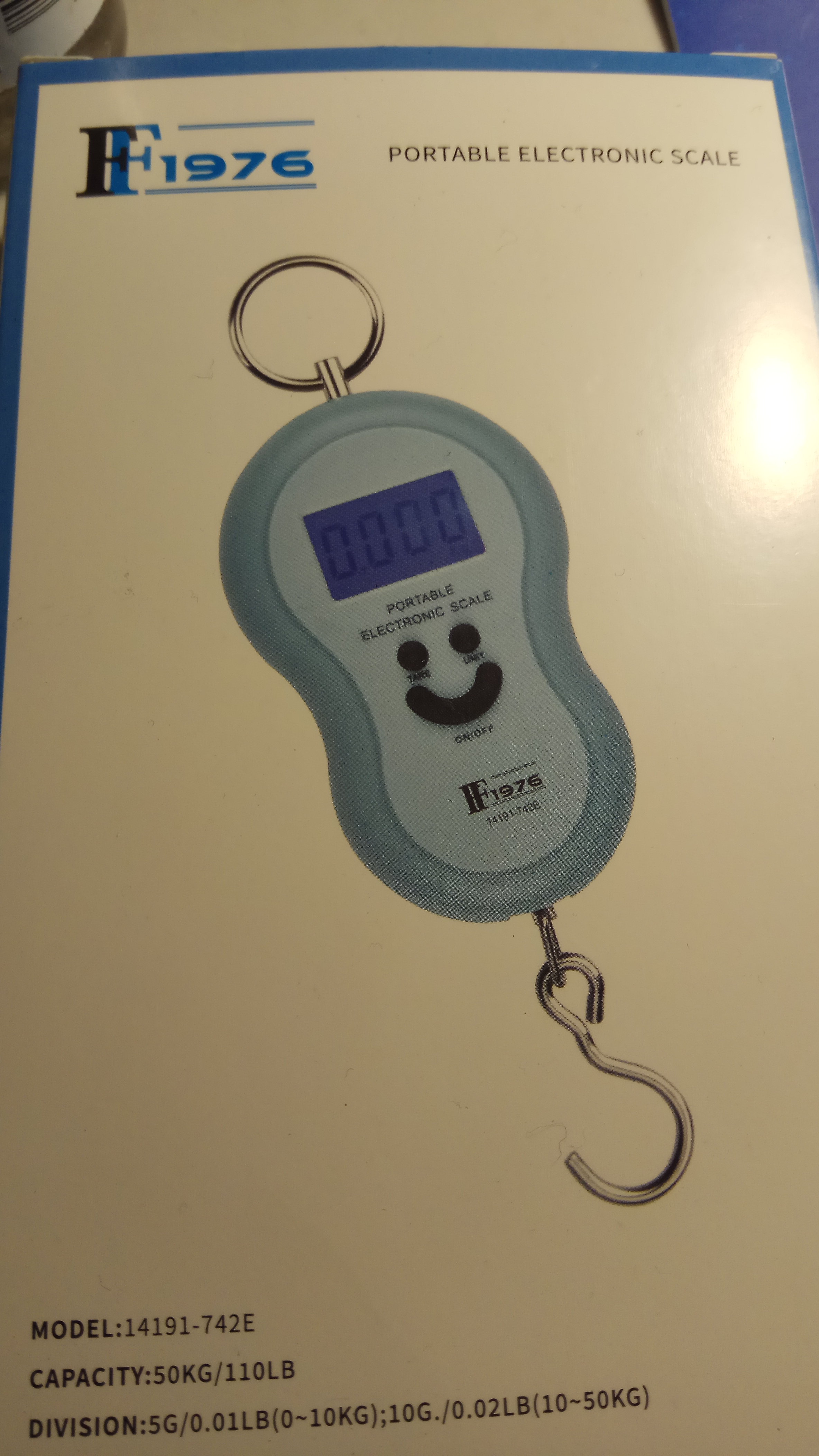
The wife found me a scale at our $ store equivalent… Good eh.
So now I can test deflection, like Chris did.

1 Like
LongMill Z-axis testing with 1.5kW spindle
1 Like
Right now, with this method of testing, I don’t have any numerical values to associate with the feed rate.
Maybe someone can comment if visually it’s comparable to the stock LM?
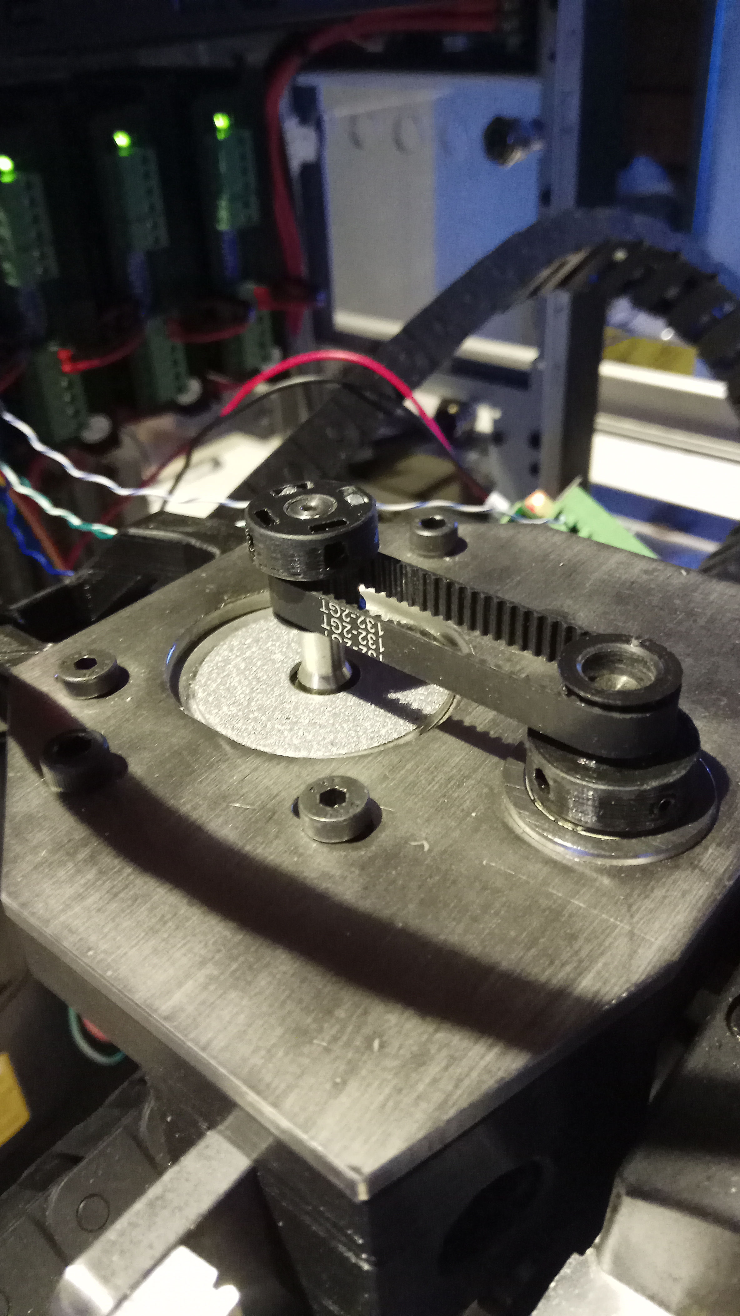
I turned to thingiverse for some temporary GT2 pulleys, since what I ordered from AliExpress hasn’t arrived yet.
I printed several different designs, but this one definitely has the best gear/belt mate, out of those that I tried.
Recommended,
[Customizable GT2 Gear / Pulley / Idler found on #Thingiverse https://www.thingiverse.com/thing:3544542]
2 Likes
Hansi, this is one very impressive build. I may be as anxious as you are to see it in operation!
Here’s another great recommendation.
Half of my anti-backlash nuts that came from China, had only single start lead thread  .
.
So to keep building, I found this on thingiverse. No modification needed. I printed it with 0.1 layer height in PLA+.
Nylon would be better if you have it. Had to break it in a bit by running it back and forth on the lead screw, but end result is a nice fit.
Linear Motion Anti-Backlash Nut found on #Thingiverse Linear Motion Anti-Backlash Nut by Arron_mollet22 - Thingiverse
1 Like
 Thanks Bill, it’s coming along really well, especially with this Corona time.
It would have taken me many evenings to catch up with the hours that I put in lately on this project.
Just found your thread. I have just discovered the LongMill and want to take a look at the STL files but I do not see a free way to access them on the OnShape site. Any suggestions how I could get the original Version 2 files? It looks like you modified them to use metric components but I have access to North American materials so the original files would work for me. Thanks
Ok wait - they hide their free membership a bit but I found it.
Ya, I didn’t have any trouble with OnShape, but I liked other CAD systems more, so I exported the model to a format that I could use. SAT and STEP are quite universal and can be imported into many solid modelers.
I used Fusion 360 for this project.
Just keep in mind that design history doesn’t really follow along with an export and some part/assembly hierarchy may not be what was designed.
But no problem. Import the model and tidy up everything.
Which CAD program do you use?
Hansi
I use FreeCad for most things. I don’t like the idea that anything I design online is automatically public domain and I am especially suspicious of “free” systems that could start charging me at any time and hold my files hostage unless I pay.
That said I found the way to get my free OnShape account and was able to download files and I even downloaded step files to use in FreeCad.
So did you make your own Gantry Plates? Did you use Steel? I would like to know how you went about it. Thanks
You’re right on the money with your “free” systems thinking. I absolutely agree with you. I’ve played with FreeCad and need some more time with it, to get more familiar with how it “thinks”.
I’ve worked with AutoCAD since high school, so the learning curve was really short for Fusion. I worked mostly “offline”, while exporting my files to my local disk, instead of saving them, which goes to the cloud. I noticed it still has some cached files somewhere, which it still tries to upload. It was cumbersome working like this, until I finally gave in, letting it upload the LongMill project to the cloud. This one is open source anyway for me.
Actually, when I came to the point of adding third party sub assemblies, like limit switches and spindles, from GrabCAD, I could no longer find a work around, other than uploading them to my cloud project file. That was the only way that I could import them, and I didn’t feel like modeling them.
So yes, I am thinking about what software to use for my projects that I will be milling on the LongMill…I don’t want them in the cloud. I may ask for permission from work to get a VPN and use Solid Edge and Mastercam, through remote desktop, after hours when the licenses free up. I’m not an expert at Solid Edge but I would need to learn Mastercam.
If I squeez in some learning time, maybe FreeCad and it’s CAM would suffice.
Ok, that was software… Open for suggestions.
My design sequence, started from the aluminum angle iron. I stretched/pulled the profile to the new dimensions while keeping the datum point, the vertex of the angle, the same. ie aluminum angle iron laying flush in all support feet.
From here I could see where the support feet needed to be stretched/pulled to avoid interferences and where more meat was needed.
After taking delta xyz measurements, I could adjust/move the existing Gantry assemblies to the new position where the V-Wheels rest on top of the aluminum angle.
With this new position being established, we can measure how much we need to stretch/pull the lower parts of the Y Gantry to match up with the larger dimensions of the aluminum angle. Depending on how the original model was translated, maybe some associations were kept, but for me everything was exploded, so I had to take care, that nothing was left behind, while doing all the shifting around.
The same procedure was done with the X-axis. This then gave me the new cut out pattern in the Y Gantry plates. I’m sure you’re aware, just work on one Y-axis, and then just mirror the final result.
Ok, I was really happy to find some ¼" plate. I’m from Israel, so everything is metric. I almost think that the plate was hot rolled, because of the scale that was on it. For me I didn’t care, as long as it was ¼", otherwise I’d have to modify more components on the X-axis.
The Y Gantry plates I had cut out at work for me, using a wire EDM. I finished tapping the necessary holes manually.
Note: I had both Y gantry plates screwed together, while squaring the stock and cutting. If I wouldn’t have had the EDM service, then I probably would have used a manual mill to cut the plates. It would have needed several setups since I’m not a CNCer “YET😁”. Else, if someone could cut them on a CNC for you, and then finish the square corners by hand.
Of course LASER is available too.
I sand blaster the gantry plates to clean them up. For the time being I have a dry corrosion protection on them, which is working really well. Planning to send all my metal parts out for E-coat, after I see everything is working. Sister in law manages a plating line, so I have some extra privileges.
Hmm… What else? If I would have had the choice, I would have looked to cold rolled steel. It would have been flatter. I did not have the Y gantry plates, surface ground, as I did the X and Z gantries. I did notice some warp in the Y gantries, but I think the V-WHEELS took up some of the uneveness.
I printed spacers, where I saw things moved away from the drive lines.
I’m sure I didn’t touch on everything, but feel free to ask.
Hansi
I replied a few days ago but did so via my mail and evidently that does not work. So here I will paste my response:
Thanks for the details. I don’t have easy access to the machines you do - I am a nurse not an engineer. I am thinking of using 6 inch aluminum channel set at an angle to the y axis. the flanges would be out of the way as the z assembly would fit between the flanges when the router is to the extreme right or left. The idea is to use something easy to machine, light weight, yet very stiff. The web of the channel is less than 1/4 inch thick so I am thinking it will work just as well as steel plate. I am still considering what to do about the Z plates. Liam
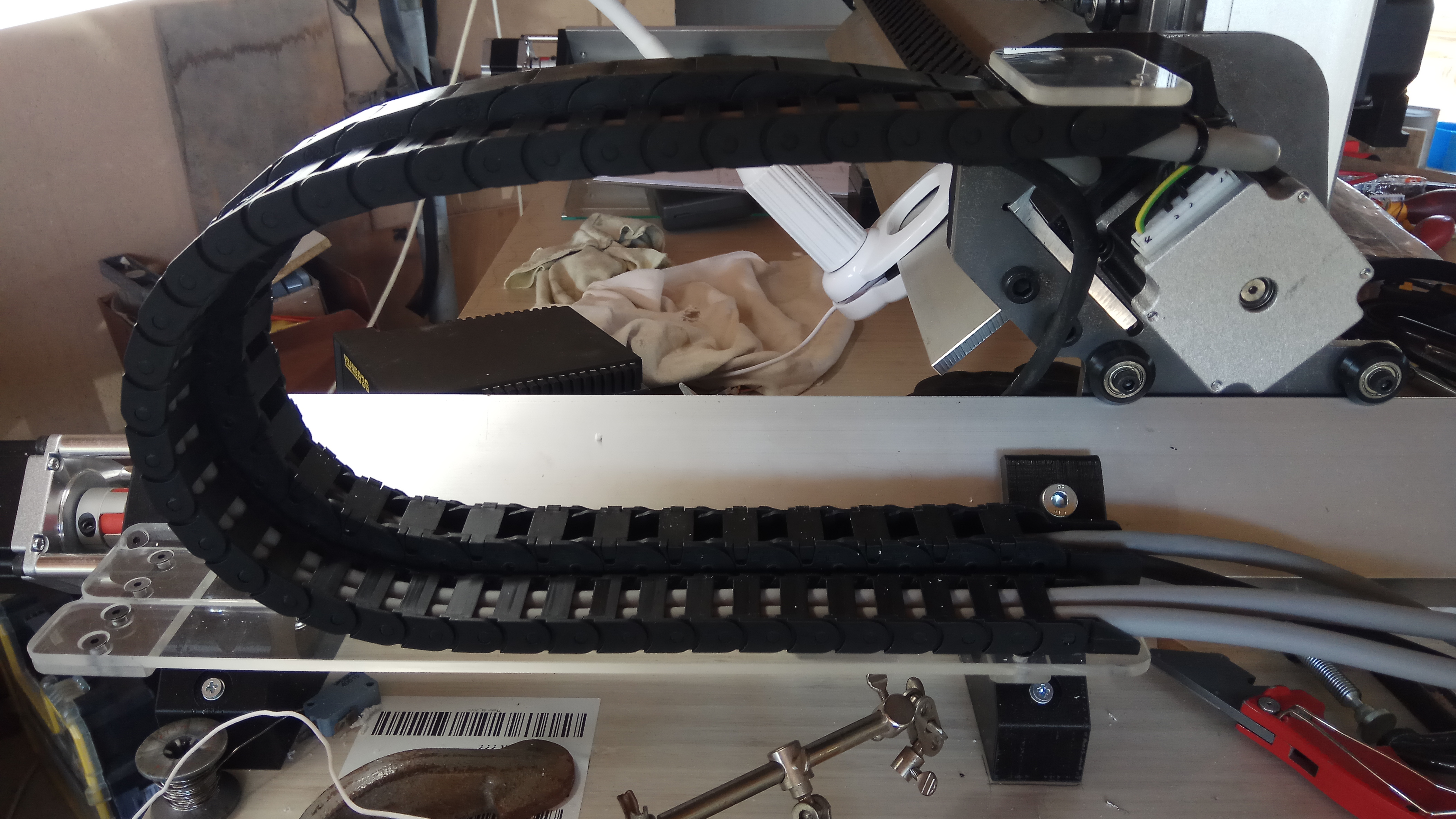
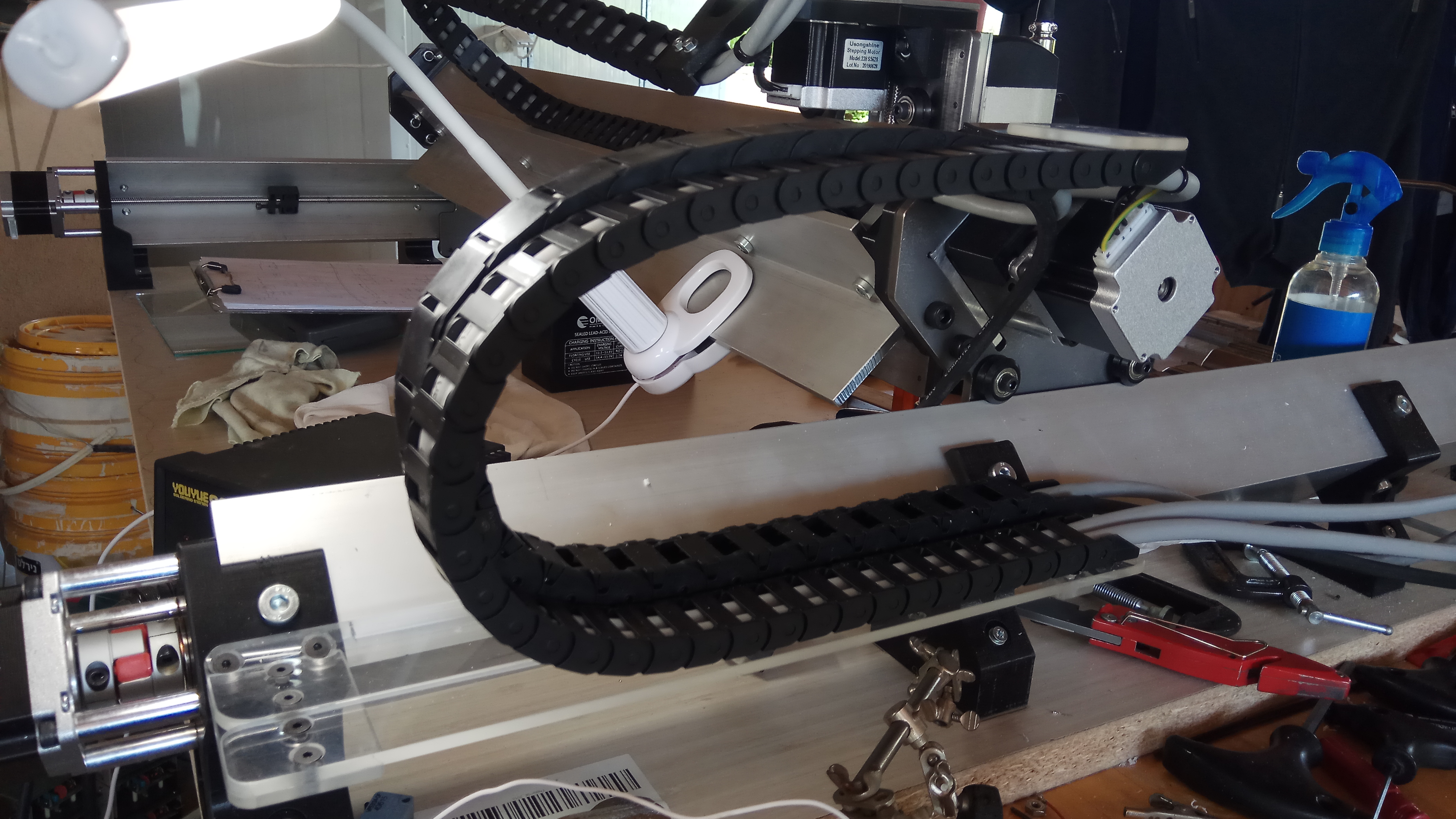
Well, had a little pause from building, since I’m waiting on some more parts from AliExpress. So I’ll post some pics of where I am…
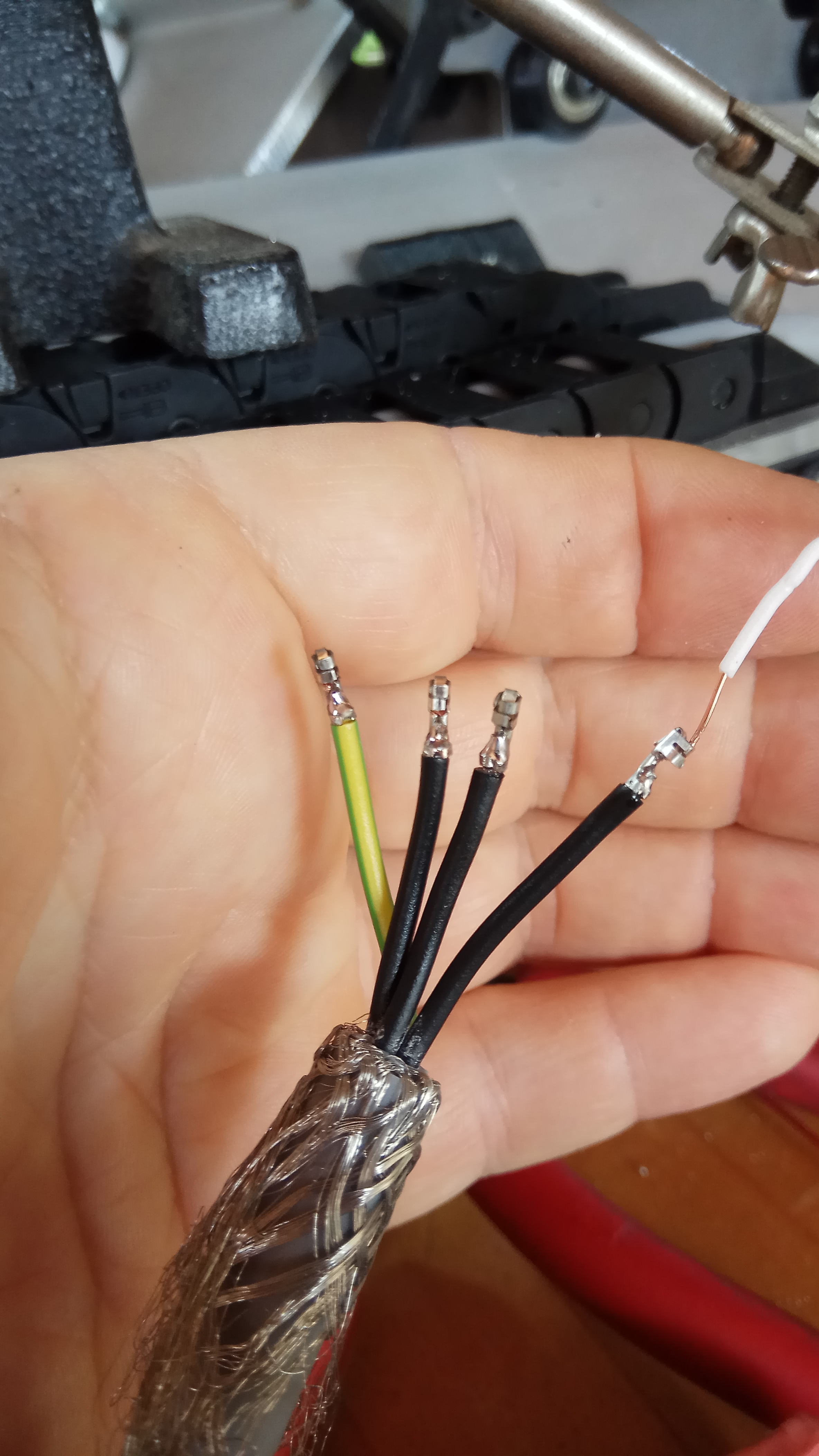
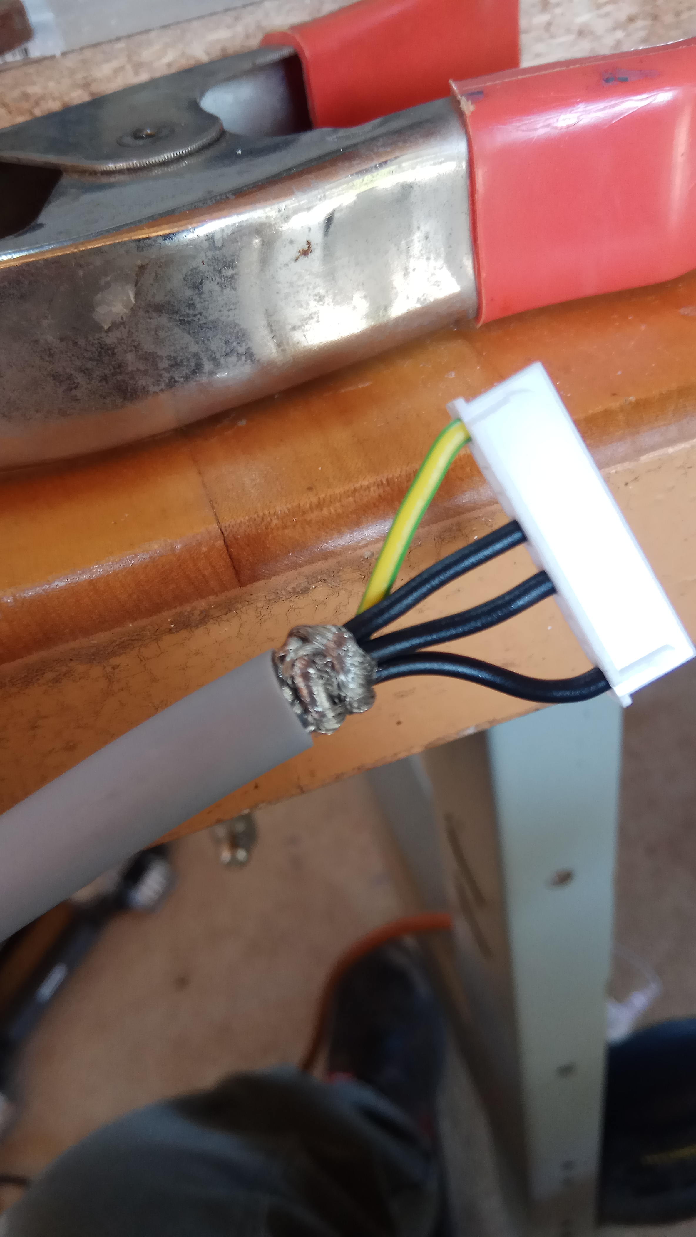
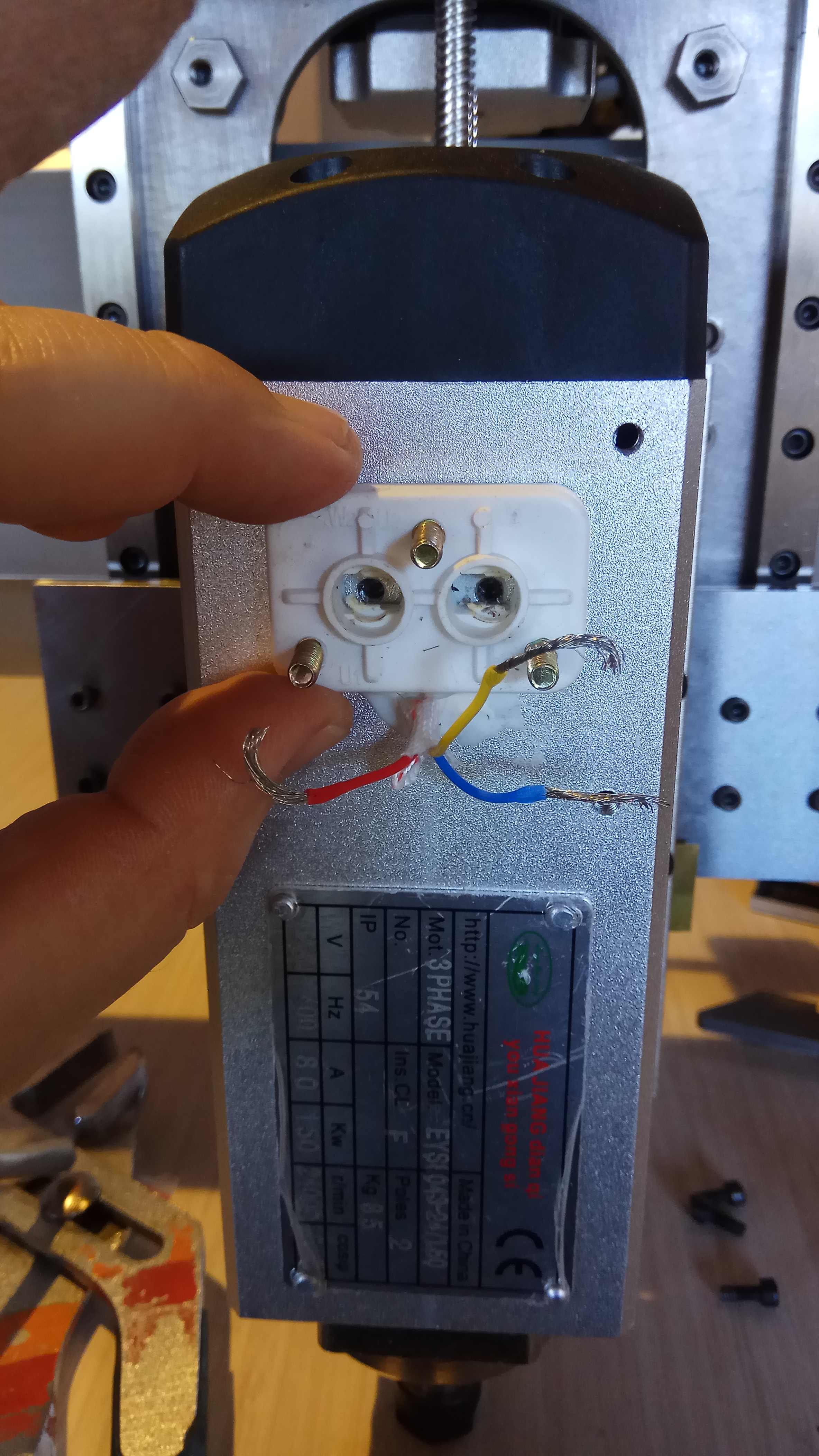
I didn’t like those small gauge motor wires that came with the JST plugs, so I extracted the crimps and soldered on directly with my 20 AWG.