I’ve made a specific part without issue setting the X,Y manually and using a probe for Z. The cam software outputs a tool change at the start so I decide to stop commenting that out manually and do my initial probe for Z with that tool change command. The first time I tried this, my part and tool bit got destroyed because the Z was extremely off. Clearly I’m missing something. Maybe it has something to do with the fact there are two steps (setup probe and probe new tool) which seem to do exactly the same thing. Regardless, I would appreciate any insight into why why I can’t use the tool change for initial setup.
This still trips me up as well, because I keep thinking that the machine is smarter than it really is.
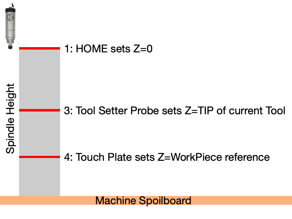
After a reset/e-stop/poweron, the machine goes back to knowing nothing:
… it doesn’t know where the spindle is in X,Y and Z HOMEing takes care of this
… it doesn’t know if there is a tool attached to the spindle (tool number)
If you are using an ATC, this information is used to select the current tool’s position in the magazine for when it is time to unload/change the tool. M61 Q# tells it what tool you have. Convention says tool #0 is “unknown” and #98 is “none”. With the RCATC, tool#s 1-4,6,8 are in the magazine, others are arbitrary manual tool change operations.
… it doesn’t know the length of the currently installed tool
At this point, the machine still has no clue as to the “Z” value where the pointy end of the tool is in relation to some reference Z position. This is where a tool setter probe is used.
… it doesn’t know where your workpiece is (X,YZ) in relation to the tool that is installed
This is where a touch plate probe is used
The combination of a tool setter probe and the workpiece probe tells the machine about several relationships:
From the tool setter: The controller knows the exact length of the tool currently in the spindle. When a tool is changed, the difference in these measured values is the difference in tool lengths.
From the workpiece probe: The controller knows the exact relative position of the workpiece with respect to the tools in use.
With the RCATC my startup sequence is
HOME            ; reset the machine X0,Y0 and Z0 reference coordinates
M61Q98          ; I start with no tool loaded in the spindle
M6 T1           ; load a random tool - the tool change macro includes a toolsetter probe sequence
USE Touchplate  ; Interactively set my workpiece X0, Y0 and Z0 with gSender and a touch plate
LOAD JOB        ; I use Vectric and the RCATC postprocessor to generate a single multi-tool nc file
RUN JOB         ; This will perform a tool change to the first tool used in the project
M6T98           ; unload tool when finished
Thank you for the detailed explanation. I went through the process a few times now. I think I was expecting it to use the current Z as to determine the current tool tip position. So, I assumed it would only need the z of the new tool. For some reason this isn’t true. For the first tool change needs the current and then, also, the new.
Changing a tool changes the relationship of the tool tip and the workpiece reference:
The first touchplate tells the machine the relationship between machine coordinate Z0 and workpiece Z0.
One could simply use the touchplate Z probe after a tool change to reset Zworkpiece. The downside is the repeatability errors that arise from an interactive process, which is why an automated toolsetter measurement process is useful.