I think maybe I’m just not thinking of something correctly here, so I figured I’d write this out and maybe someone would point out my bad assumption.
I used the squaring wizard to square up my 4x4 Altmill, I had it travel 900mm in both x and y and it measured out at 900mm exactly in both directions and was square as built (Yeah!).
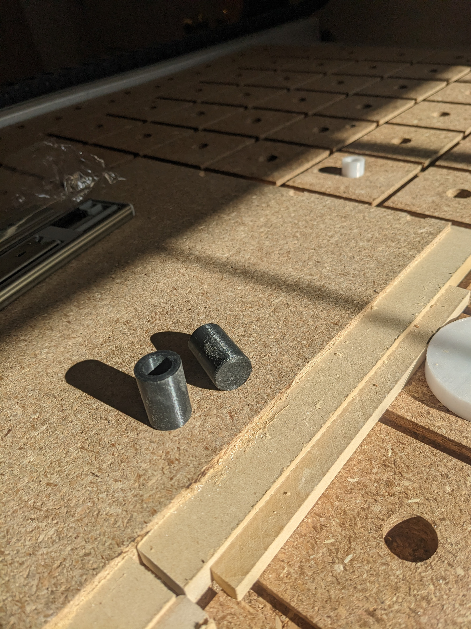
I’m doing a matchfit style spoilboard with dog holes in it, I’m going to use PVC pipe sections as my dogs, so I was using a 1/8” bit to cut the circles, I measured the pipe to be 21.28mm with a set of calipers, so in Easel (I’m using Easel for easier stuff as I find Vectrics interface super clunky, why can’t I keep a property sheet up for objects to edit size and position all the time instead of having to do multiple clips for simple/common operations) I drew a circle with a diameter of 21.3 mm and then did an inside cut figuring that would make a circle who’s outside diameter was 21.3. The resulting cut in MDF was around 21.05 and the PVC would not fit, I had to make the hole 21.8mm in Easel for the cut to work, or .5 mm over sized. A 1/8” Bit is 3.175mm so it’s not half the bit or anything like that. And given that the travel measured correctly over a 900mm distance it seems odd that it’s off a small distance.
@gremlin I’ll second what @Chucky_ott said. Also, I would very much doubt that the PVC is a consistent diameter throughout its length. You are allowing only .02 mm or less than a thousandth of an inch clearance.
@gwilki@gremlin I also wasn’t sure about the diameter of PVC pipe when I did my dog holes. That’s why I used PEX instead. I assumed that since PEX fittings need to fit inside other fittings, they would have a more consistent diameter. PVC pipe is solvent welded so diameter is less important. I also think PEX is rigid enough for this purpose. But a lot of people use PVC. You just need to account for different tolerances.
bit measures out at 3.15 so it’s a bit smaller .02 smaller don’t think that’s it. Also the piece of pipe I’m measuring is the same one I’m putting in the holes, so I don’t think it’s variation,. the hole as cut btw measures 0.2mm smaller than requested. Should be fine for most stuff I’d guess
Maybe try a engraving bit or vbit to make a shallow pass in the spoilboard where a pvc has to come and measure that one to zoom in on what the troublemaker might be.
Maybe even do a single one in vectric to see if vectric has the same problematic offset.
Usual preface, I’m with PreciseBits. So while I try to only post general information take everything I say with the understanding that I have a bias.
Without knowing more I’d guess that you are dealing with deflection (bending). It would be hard to say without at least more info on the chipload and tool (feed and speed plus flute count and general tool geometry). However, generally speaking the cutting forces cause the tool and machine to deflect as you are cutting creating dimensional inaccuracies (everything is a spring). You could try doing a cleanup/spring pass to try and get it back in spec with the assumption that the code and tooling is correct. It’s going to be harder with easel as I don’t believe they have cut direction control (been a long time since I checked though).
Some other options would be to reduce the cutting forces. Cutting forces are more or less proportional from chipload (feed), stepover, and pass depth (though in different directions). You can actually get in a worse situation with reducing chipload if you are rubbing where more force and heat get generated. So the easiest thing to do is to cut the pass depth. For stepover if you are slotting it’s your tool diameter. So you end up in situation where you have to decide between a stronger tool or a lower cutting force. Until you reach the limits of the machine if you can use a bigger tool that will typically win on the rigidity side.
One last note. I don’t recommend ever physically measuring a tool. See here:
Your best bet is to cut a slot and get your actual cutting diameter that will include things like your runout and material compression to know what you are actually cutting.
Hope that’s useful. Let me know if there’s something I can help with.
At the risk of exposing that I am a Luddite, I went the other way. I made my holes and then 3D printed dogs (multiple sizes) until I found a size that fit with just enough friction for my taste.
IMHO, all the PVC (at least of that production batch) are the same size so I would bore test holes in some scrap wood until I found a size that works. That takes care of any deflection that you get from cutting forces.
I hear ya Jens. I prolly wouldn’t care much either if I had deflection or a bad mill diameter, but a machine not accurate enough to mill my design to spec, that I would like to know. Hence my suggestion to use a shallow pass with a pointy milly to see if it is the machine.
If it turns out to be either the mill diameter or deflection, i would just shrug and dive into the temp tool settings and set the tool diameter smaller untill it milled the holes I need.
Or what you did, if I had a hammer that could 3D print.
@Jens Thanks, that’s what I wanted to do but I was concerned about trying that, how do you print the dogs? I was thinking the obvious way if you want them to be flat on one side out of the board is to print them upright, the same way they go into the spoilboard. If, however, you did this, then the layers are what get put in shear force by the clamping forces and the layers are the weakest part of the print, so I was concerend they’d just break across the face and then you’d be stuck with the broken part in the board.
@TDA thanks for that info I would doubt that’s it as the holes do look nice and clean. I was running a 1/8” Downcut bit at the manufacturer specified speeds and feeds through the MDF it was 2700 mm/mi feed with 1/2 that for plunge and 5.5 mm depth per pass (looking back that one does seem aggressive), anda. 20 degree ramp , and I was running 17000 rpm wiht a default milling direction in Eassel (you can set that). the holes look clean and very very round
Until deflection gets really out of control it will look like a good cut. The amount you are talking about here won’t be obvious. It’s also not really an aggressive cut. That’s about 1.5x the rule of thumb number for a minimum. Plunging in the ramp also gets rid of the most obvious sign of deflection (depending on the cut direction).
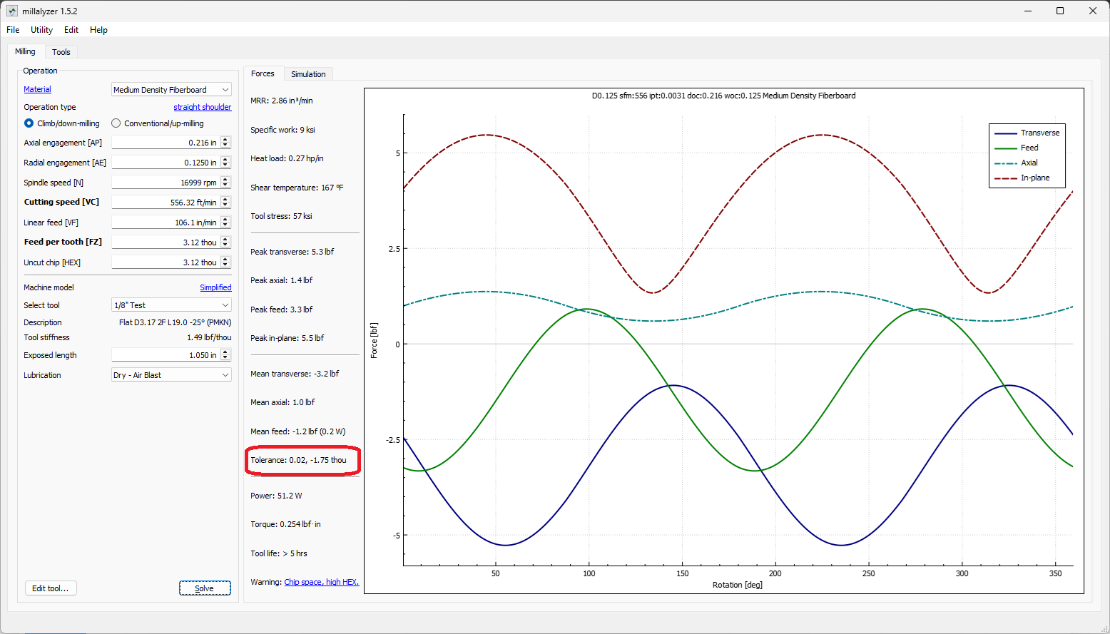
As an example here’s what that looks like in millalyzer assuming a 0.50"/12.7mm length of cut, generic geometry, and a normal stickout.
You are doubling the error as it goes in both directions and true deflection numbers depend on the stickout, carbide grade, flute depth (core), runout, etc. That said though, unless it’s a much more whippy tool than this it’s unlikely the issue in a 0.010"/0.25mm small hole. Even in this “long tool” example you only get about half way there with this plus the assumed correct tool measurement.
The idea of taking a basically no load cut (tip of a “V” cutter) will also give you most of the answer. While I was doing that I’d also cut a slot with the tool and measure the slot width.
Yeah, especially for a one off. Realistically if it doesn’t need to be repeated knowing what’s an issue might help in the future. But getting the job done is most important.
I print them exactly the way you think, upright (but upside-down). I have an ever so slight taper on one side (for easier insertion) and when I print the dog it is with the flat side down to get a better/cleaner taper. It also eliminates any issues of elephant foot.
There are a couple of gotcha’s I have encountered. I first printed things in PETG (my default material) which can move/distort more than PLA. I first printed the dog with a fairly thick outer wall (probably 3 mm) but found that if you get carried away with clamping forces of your stock from the side, the dog will deform. In most cases this is not an issue but for those occasions that require more precision (double sided work where the dogs are used for precisely locating the work piece)) I print the dog mostly solid. I have a section up on the top that still has the wall with the hole in the middle which I can grab with pliers to pull the dog.
I have never run into a dog shearing and should it break off, it is relatively easy/quick to mill the dog out (don’t try milling it out completely - leave a thin wall so you don’t screw up the dog hole)
Can you post a picture of one of your dogs? The one thing I’ve done was mill my board as rings, not holes for the PVC, I think if I 3d printed, they’d need to be solidish. If you’re not using PETG what are you using now? I tend to use ASA for heavier things, but I wonder if TPU would workbetter
Ugh … definitely TPU is a No No (with bells on)
Regarding ‘rings’ - how deep do you seat the dogs? My holes are 3/4"deep, the full depth of the spoil board. Doing rings is impossible at that point.
If the dog is not inserted most of the way in the hole, there is a good chance that the sideways clamping pressure can push the dog over by a bit (making it sit at a slight angle)
I now use PLA. I think (but do not know for sure) that ASA has flex similar to PETG.
Correction on my wall thickness - it is 4 mm
I do not recall what I used for # of inner and outer walls nor what the infill percentage was but based on how accurate you want things to be, you can vary it from about 15% (least accurate) to 95% (most accurate). The solid portion of the dog is about an inch.
I have two kinds of dogs - the ones that position the eccentric don’t need to be filled in and if they bend slightly, it matters not.
Another thought - I clamp with side force but if you only use the dogs to position the work and clamp with vertical pressure then none of this matters.
I am guessing that PVC pipe also has some give so sideways clamping could possibly be a problem in high accuracy situations.
I was going to do 9mm half the board depth as I was trying to avoid the fastening screws which are sunk to 11mm. This is my first shot at doing dogs so that may fail but o saw someone else doing the rings and thought it looked good and since you’re supporting the pipe outside and inside felt it might be more stable
In my case the fastening screws are intentionally in different locations …
The only thing I can suggest is to try it your way and see what the result is. I haven’t tried your method so I might be way off and as mentioned before, if you are not planning on clamping your work horizontally, then 9 mm will be just fine.
Yeah I thought mine were out of the way, but they didn’t end up there, I spaced on cutting them as I wanted the machine to cut them for me from the machine zeros so that I could re drill new wasteboards and know they’d end up in the same place. The wasteboard is from it’s corner zero so that I can have some marks for sizing info
As for the not clamping horizontally I’m not sure I grok what you mean by that, the only way things are clamping to a dog are by pushing against it horizontally. We’ll see what it does, I can always hog out more, now that I’ve removed the ones that conflict.
While I agree that the normal method with dog holes is pushing horizontally, you also talked about the matchfit system and that can easily be used for clamping stuff with vertical force. I use a variety of methods for workholding including dog holes, matchfit clamps and double sided tape.
I also have used the dog holes strictly for positioning and not for work holding.
I have pre-drilled all my mounting holes so I have a file of the exact locations and can easily re-create mounting holes on a new spoil board. The holes are with reference to the mill frame which never changes.
Please be aware that machine zero (ie home position) is not a fixed reference point. It depends on the sensors and their location - it could be as simple as one of the sensor nuts loosening with use which has happened to me. Once tightened up, it is unlikely that your machine zero is at the exact same spot. You might be within a mm which may or may not be accurate enough for your use.
I should add that I also have a file for the mill table (the surface below the waste board) so I can easily re-do that as well. The mill table is attached from the top and the mounting screws are countersunk.I have tapped some of the factory holes on the stringers for the attaching screws.
Gotcha, my plan is for the dogs to allow for square alignment but also some clamping force by pushing against them from something in the match fit t-track, also I was planning to cut some holders that would fit the dog holes as well to help with other things, like tiling. Again, first time sort of a combo of what I’ve seen others do. As for machine zero, I actually moved it forward as far it would go and kept X off the home, but you are correct hat might get changed. In my case I have the new sensors which can’t move as easily but it’s something to watch for.
I noticed I missed some other replies above, I did actually do a test carve piece, that’s how I figured out the sizes were off, and I cut several steps to determine the one to use for the final board. I may find now that I should go deeper with these which I can certainly do.