Alright, editing this post to show the project I actually made.
Design:
First step was to use some digital calipers to measure my t-nut that I ordered. There are a couple measurements required. Since I want the t-nuts to sit flush in the bottom of the waste board, I need to know the diameter of the base, as well as its thickness. The diameter will be used to mill out pockets for the bases to sit in the base or the board. I also needed to know the diameter of the thread part so I knew what size holes to drill all the way through the board.
Having fiddles with carbide create a few times I then decided on a workflow that would make the design process easy.
I created a workpiece with a size of 30" square. Also, I measured my stock thickness here - it was .770 inches, so a little thicker than 3/4".
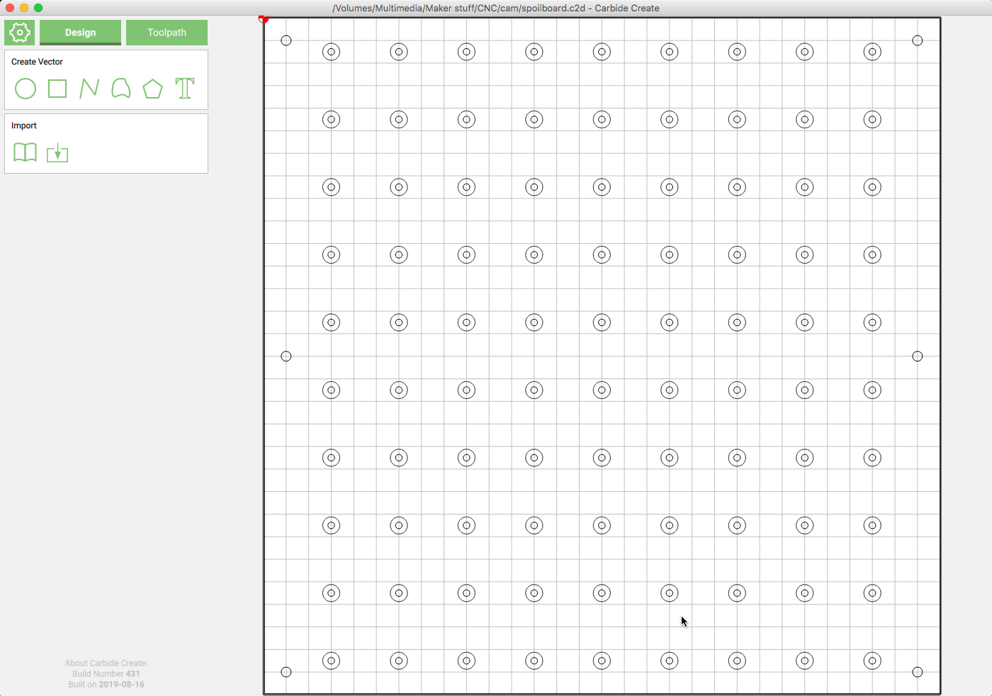
Next I created the first through hole, with a radius of .148 - as the measured diameter was 2.96 and I want these to be pretty snug.I then created 8 copies of this and spaced them equally across the spoil board. I then copied that row and copied it down, etc, until I had 10 rows of the holes (The reason I did not have 10 going across is so I would have more room on the sides for screws to hold the board down to the machine)
Once those were all created I then grouped them together, as they would all be part of the same toolpath.
Next I created the pockets. Selecting the previous group, I then did an offset. I knew the pockets needed to be about .753", knowing that, I got the radius of the pocket and subtracted out the radius of the drilled hole to get the offset amount (.756 / 2 = .378 - .148 = .23) doing this offset will create a new circle around the entire group of holes, once that operation was complete, I saved the resulting circles as another group.
Next, I created a hole with a diameter of .22 inches - This will be drilled out down .7 inches into the top of the spoil board in order to hold it down to the machine table. I copied this hole 5 times spaces them in the board, and grouped them together as they also will be part of the same operation.
Finally, I create a 30" square rectangle, and aligned it with the workpiece. This will be used to pocket out the entire board to level it, and, if you are like me, you will also do an inside cut on this to cut the spoil board out of a slightly larger piece of material.
Tool Paths:
Now that the geometry is created, we can create the tool paths. For this project it is important to note that there are tool paths for the back side of the board, and tool paths for the front side as well. I also used two different bits, a .250 down cut end mill, and a 1" surfacing bit.
For the back of the board, I started with the pockets first, select that group. If you have trouble selecting groups, return to the design tab and select the group, then return to the tool path tab and the group will stay selected. Referencing my measurements, i knew the t nuts would need to be .07" down into the board to sit flush.Choose the contour option, then select the .250 (#201) end mill, select “Pocket” as the operation, and set the depth to .07 inches. I set the feed rate to 40 inches and the plunge rate to 12 inches, not really knowing but feeling these were pretty conservative numbers. Give this tool path a good name (Like bottom pockets) and save it.
Next we will drill the through holes. Again, return to the design view, and select the group containing the holes. On the tool path, we will select Contour, then choose “.76” as the depth, remembering we set the stock depth earlier to .77 inches. and, we will set the “Start Depth” to .070 since we will be running the pockets first, and will have milled away .07" of material from that operation. I used "Inside, Left` as the offset for this operation. These holes will likely not all e bored through the waste board, but we will be taking about .08 off the top to level the board later and this will expose all of the holes. I used the same speeds as the pocketing operation.
That is everything for the bottom of the board. This is a good place to note that you can right click on the exiting group name and name a new one - I had two groups, one for the top and one for the bottom. this will make it easier to export the g-code later on.
Select the 6 holes we will drill into the top of the board. I just used the same .250 endmill, same speeds, and a max depth of .4 so the screw heads will be well recessed.
Last, I defined the surfacing operation. Select the rectangle that we drew around the entire work piece. For this operation, you will likely need to add a new bit to the tool library. My surfacing bit was 1" in diameter, with 3 flutes. I set the step-over to .4, the depth per pass to .1, the feed rate to 20, and the plunge rate to 5. I set the max depth to .08. This will be a “Pocket” operation.
That should cover the toolpaths, lets talk about running it on the machine now.
At the Machine
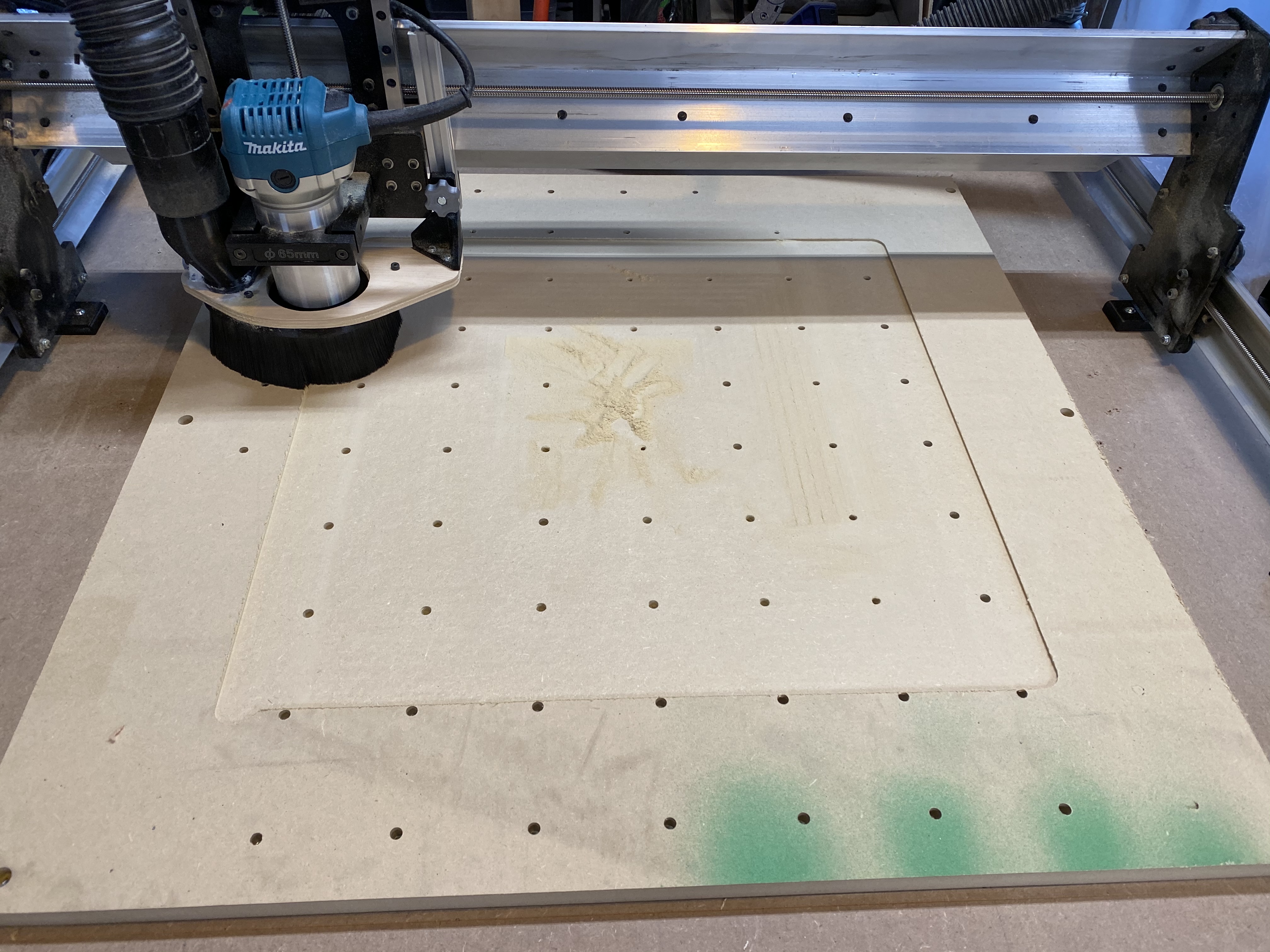
I secured a 32X32 piece of material to the bed of the machine - I indexed the long mill at the farthest back and left position the gantry would go, that is what I ended up using as my zero as well for this particular project. I clamped it in place by screwing some pieces of plywood next to the MDF I was using. I set the zero in carbide create to match the zero position of the machine, disabled the top tool paths so they would not be exported, and rest zero with the .250 end mill touching the surface of the MDF. I then ran the g-code out of UGS (Universal G-code Sender).
This will mill out the pockets and drill the holes if you have done everything right to this point.
Next, in my case, I actually decided to insert a new operation prior to flipping the board over - I decided to cut it out now, as opposed to later. There were a couple reasons for this, but mostly, I was concerned with holding it own and re-aligning it later. So, I went back to carbide create and made a new tool path to cut along the inside of the 30" rectangle to cut out my spoil board. This results in a 29.5" inch board, but that is ok, at least for me. To hold it in position i grabbed 4 t nuts and put them in close to the edges, maybe 2 rows in. I put in 4 total - Then I was able to get some normal screws and run them down into the t-nuts, the screws pass freely through the t-nuts and crew into the wood, making the n-nuts act like a washer. I then cut out the board.
I removed the extra material from the cut off - then to maintain alignment when i flipped, I took my screwed down clamps, and moved them back in to be flush with the now smaller board and re-screwed them down. I then removed the screws in the t-nuts and flipped the board over.
With the board flipped, I ran the operation to drill out the recessed for the hold down screws. With those done, I put in 6 1 1/4" pocket screws into those holes. Now the spoil board is held down. Knowing that the next operation will resurface the entire board out to the edge, I then removed my clamps, giving the bit the clearance it needed, changed the bit, re-zero’d and ran the surfacing operation.
That about wraps it up - Sorry for the long-winded post, if you have any questions would love to answer them.
Mike
Here is the link to the carbide create file