Surface Height Map for gSender
Latest release package: here
There us another version of this that starts with the upload of an NC file: Here
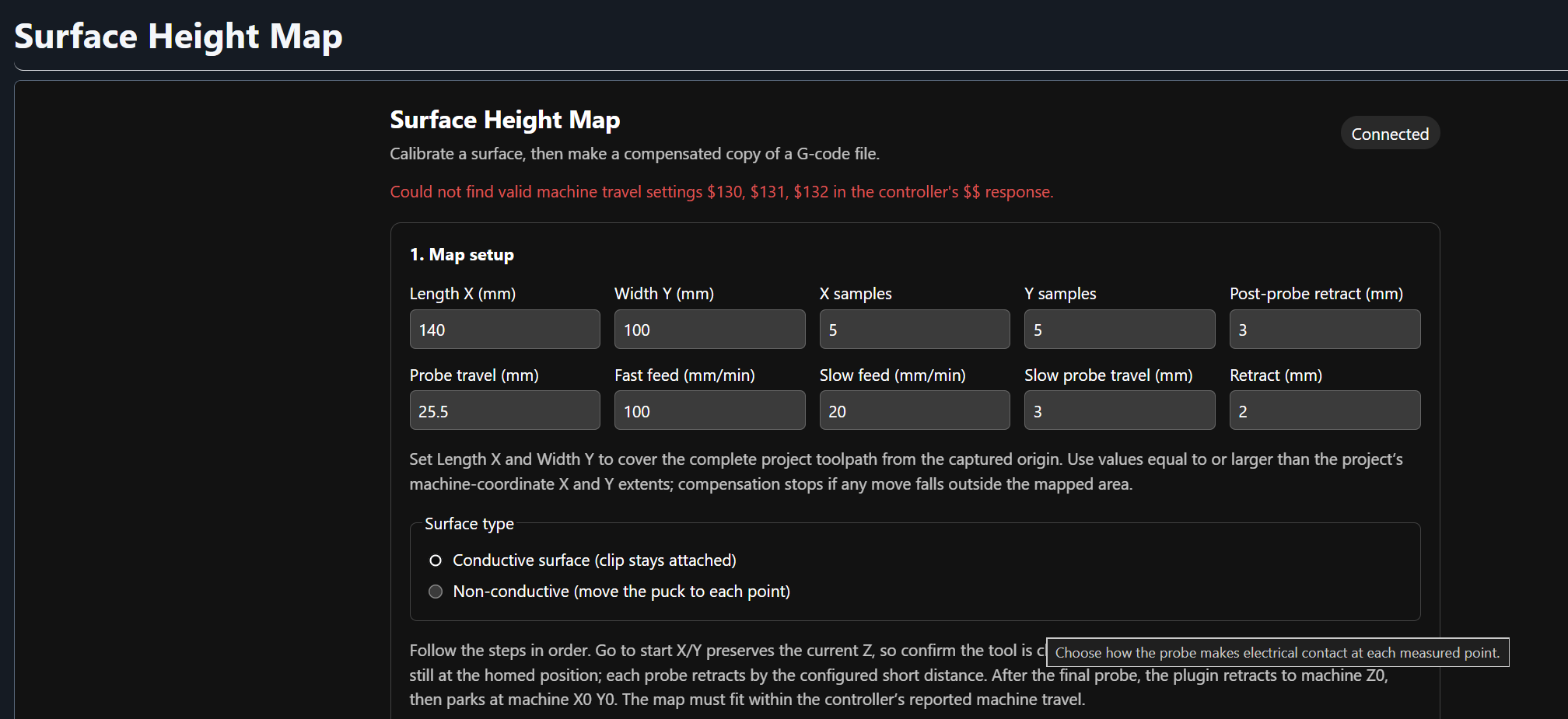
Surface Height Map is a community gSender plugin for measuring a work surface at a regular grid of probe points, then applying those readings to a supported G-code toolpath. Calibration is saved independently of any one job, so you can map the material or spoilboard once and use that map to preprocess files whose XY footprint fits inside the mapped area.
The plugin creates and loads a new compensated copy. It does not edit the selected source file. Its first supported workflow targets metric, absolute, linear G-code on GRBL-compatible machines.
@bakStaaJ Thanks for creating the new thread. I tried the plugin and had a few issues.
Before you can do the height map, you need to home and then set the CT zeroes. Homing works but I can’t move to any location. If I enter values in the dialog boxes, nothing works. So I’m stuck at the homing location (rear left).
That said, I’m not sure why I would need to home and set zeroes. I would have those already done before running the plugin.
And I don’t know if it will work with the 3D probe that I have.
Are you getting any red error message at the top of the page?
I made an update to detect that machine is already homed and reduced some of the button clicks - gSender-Plugins/surface-height-map/v0.1.30 at main · bakstaaj/gSender-Plugins · GitHub - hopefully this works for you
@bakStaaJ Better, but still issues. Using anything other than 0 and 0 for the coordinates does nothing. If I enter a negative value for Y, it does not move. If I enter a positive value, I get a soft limit alarm (which is expected because the machine coordinates for Y must be negative). If I enter 0 and 0, it moves to the machine zeroes (not the workspace zeroes), and starts the probing sequence. It detects the probe but I didn’t check the spindle movements since it was at the far back. The probe was in my hand though and I could trigger it for the next probe. Should it just not use the workspace zeroes instead of machine zeroes?
If you run $$ in the console what does $23 value show for your machine?
@bakStaaJ I’m not at my machine but it’s probably 1 for the rear-left. That is the default homing location for the Altmill. I’ll confirm tomorrow morning .
I was not reading the $23 setting - just using what my machine had which is $23=3 - this version now reads $23 and adjusts accordingly - Hopefully that works. gSender-Plugins/surface-height-map/v0.1.35 at main · bakstaaj/gSender-Plugins · GitHub . The plugin uses machine coordinates because the map is tied to fixed physical locations on the machine bed, independent of the active work offset (G54, G55, and so on).
@bakStaaJ Thanks for that. Progress!
Now it moves to the coordinates chosen but when it starts to probe, the spindle moves from back to front instead of front to back. Since my workpiece origin is front-left, probing would completely miss the workpiece.
Also, instead of manually typing in value to move to, can it just read the workspace zeroes (or workspace offsets as you call them) and use those?
@bakStaaJ I wanted to do a real height map on a bent piece of plywood but broke the tip off my probe. I existed the plug-in page to do a jog and when I returned, I forgot to enter the origin coordinates. Since it defaulted back to zeroes, it did a rapid move to the rear-left and hit something on the move over.
I think using the machine coordinates instead of the workspace coordinates could cause problems and I’d be reluctant to use it that way.
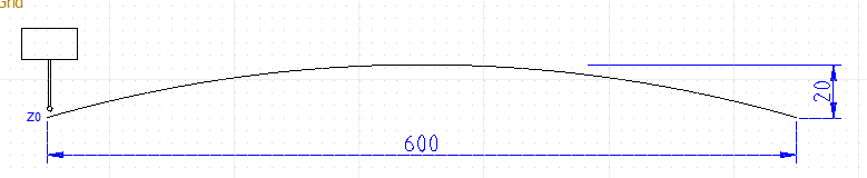
Anyways, the bent piece of plywood had a z differential of 20mm. The Z0 was at the bottom of the workpiece. I changed the retract distances to 25mm but it didn’t appear as if it moved that height between probes. So I stopped the probing sequence, exited the plugin to jog back to x0y0. And that’s when I broke the probe tip when I returned to the plugin 
Just tested again and it doesn’t appear as if it is respecting the retract distance between probes. In fact, it doesn’t look like it is retracting at all from z0 between probes.
Unless I misunderstand what they mean.
FWIW, for the ncSender plugin that someone else developed, if the probe hits the workpiece as it moves between probes (because the retract distance wasn’t set high enough), it will retract further. At least that’s what my test showed.
Sorry about the probe - PM your venmo and I will buy you a new one. I was trying to be too cute and reduce the amount of settings that were needed - Assuming the machine was at full home (including Z) when the calibration started - it used the starting Z position as the baseline for the between probe retracts - anyhows - I added a parameter to set the between probe retract height - gSender-Plugins/surface-height-map/v0.1.36 at main · bakstaaj/gSender-Plugins · GitHub and made the X/Y start point persist. Sorry the machine coordinates wont work for your use. I truly appreciate the testing.
@bakStaaJ Don’t worry about the probe. It’s just the tip that bent, and when I tried to straighten it, I broke the ball tip. It is supposed to be tungsten. Either it was glass, or tungsten is really brittle. I can easily replace the tip with a new one or I can just use a 2.5mm x 0.45 bolt with the head cut off. I’m just using it to probe z, so the bolt will work.
I’ll try the new plugin with the broken tip. It’s still useable.
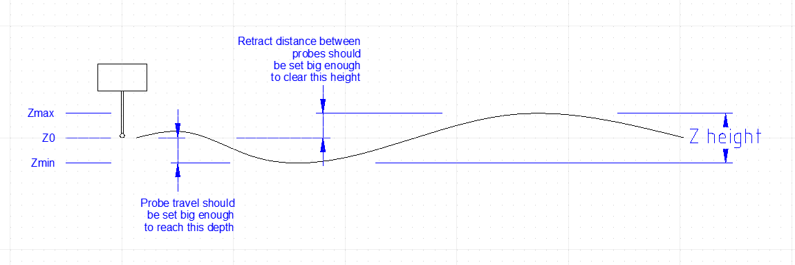
What were the previous values for retract and travel used for if not for movement in between probes?
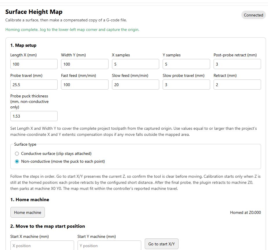
The Post-Probe Retract was to move the head up before returning to the home position after all of the probe points were completed - the retract was the retract in the middle of the double tap. There was no setting for the retract between probe points ( was auto set based on where Z was when the calibration was started ) - In my original workflow - I always homed the machine right before starting the calibration, That is why I had the home button in the plugin so I could progress right into calibration immediately after homing. In this latest version I force the head to Z0 machine before moving to the first touch point and again after the last touch point, then have the 2 retracts (Full and Short) settable. Note the full is again in Machine Coords and the Short is distance above the touched reading - There is a description of each field if you hover over the input boxes
@bakStaaJ Unfortunately, at the start of the probe, it moves to machine Z0 (at the very top for me) and never goes down to the work piece unless i have a probe distance of like 150mm. And I have to enter a negative value for Z retract in order to not get an error.
@bakStaaJ I managed to get it to work but I have to keep the “full retract” at 0 and the “probe travel” at 150. I tried other values but kept getting alarm 2. With those numbers, I have to live with the fact that the spindle will move to machine Z0 at each probe.
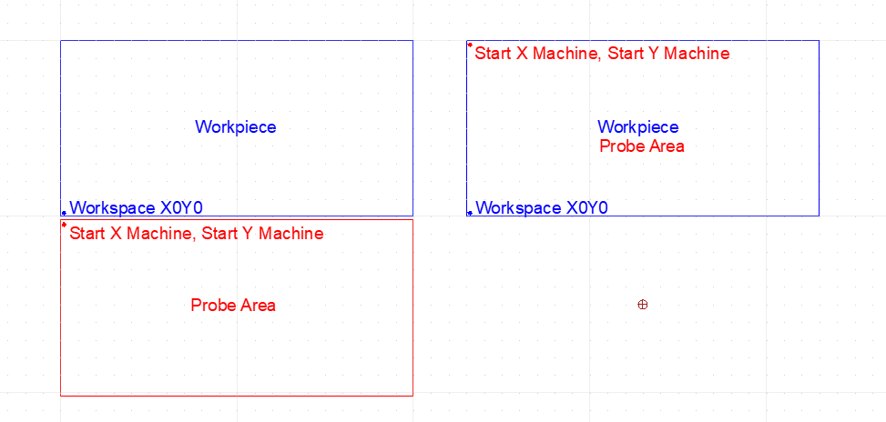
And as mentioned in a prior post, the second row of probes goes to the front of the machine instead of the back. This means if I set the probe origin to the workspace origin, it will not probe the workpiece. To probe the workpiece, I have to the “Start X Machine” and “Start Y Machine” values to the rear-left of the workpiece.
In the left image below, the red and blue dots are actually the same machine coordinates.
So this finally got me a mesh. But then, when I tried to apply the compensation to a g-code file, I got a “mapped area” error. I tried several files (one with an area less than the probed area, one with the same size) and got several different errors.
The use of machine coordinates instead of workspace coordinates makes it difficult to use. Too many offsets need to be thought of when figuring out the numbers to use. I would want all the numbers to be based off Workspace X0Y0Z0
That is correct - If you have a large Z stroke - the Probe Distance is the maximum that you are willing to let the probe travel without a signal - I set mine to my maximum Z travel. The Full retract is a negative number Z0 at the full Z height - Negative moves down toward the work surface. I leave mine at 0 - If you dont want it to retract to full Z height you can set a -value i.e. -10 = 10mm below full height.
@bakStaaJ Yeah, I tried -50 but that’s when I started getting Alarm 2’s depending on what I used for the other numbers.