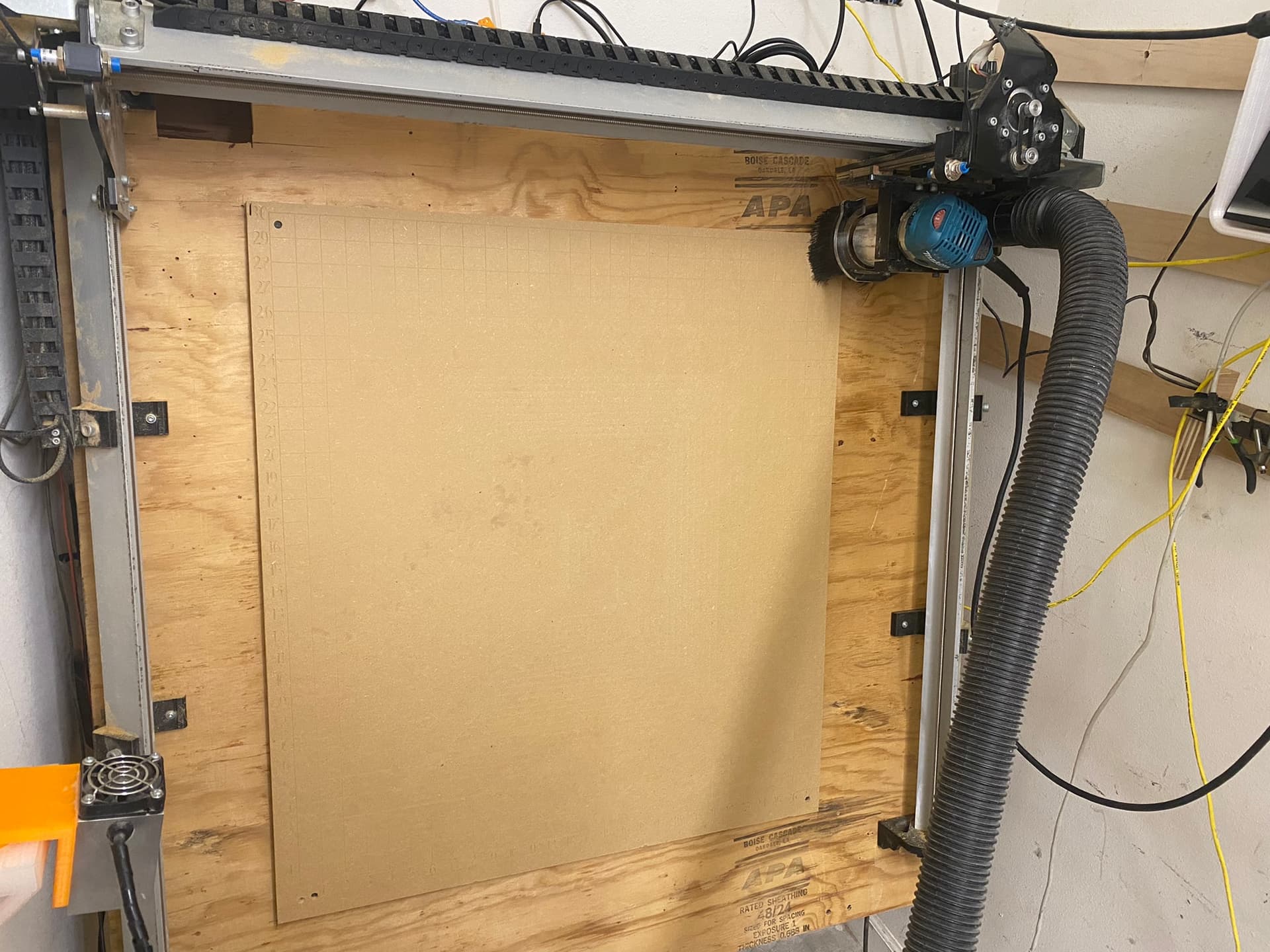
After surfacing with a regular 7/8" surfacing bit my spoilboard has a noticeable dip in the center. As seen in the photos when I add the reference lines with a V-Bit only the outer edges of the design actually cut into the board. My carves also cut out unevenly, cutting into the spoilboard towards the edges and not completely cutting all the way through the project as it gets closer to the center.
This is my second spoilboard since buying my Longmill and I’ve had the same issue with both. My previous setup was horizontal, so I don’t think it’s an issue with the machine being mounted vertically.I’ve also replaced my surfacing bit after my first spoilboard. Any help would be appreciated.
Hi Josh. There are several places in which you can look first. The baseboard which have bolted your machine to may not be truly flat and it may have a dip in it. The spoilboard looks to be quite thin and may also not be entirely flat, where it may be following the contours of the baseboard. The larger the material used, the more likely it is to be subject to a degree of warping, although MDF is not usually subject to this issue unless it is in an atmosphere which contains a high humidity level. It is common for MDF spoilboards to be at least 18mm (3/4") in depth.
The fading index lines tell their own story because they disappear quite a short distance in from the spoilboard edges. Insufficient cut depth will be partially responsible for this aspect of the spoilboard. Even some of the index numbers are not visible which partially supports this cause. There is a clearly marked square of lines in the MDF. It is more noticeable on the right and the top of the image near the centre of your spoilboard. These machining lines indicate a tramming issue.
I don’t have this particular machine so I have no idea how your machine base is supported. I would want to check that this is really flat… not so much for the whole room but within itself. This must be as near to flat as it can be. Levelling it to the room is next and it will help you to feel that you are intuitively working with a square machine.
A close up photo of the machining marks in the centre of the spoilboard and an indication of which direction is the front of the machine will help to determine in which direction the tramming is out. e.g. if the individual machining marks are sloping upwards from front to back, this indicates that the trim router which you are using as your spindle is out because the top of the router is is leaning forwards in relation to the bottom of the router.
You will not lose these machining marks until your router is perpendicular for both pitch and yaw. This displacement will also wear out your cutters more quickly, cause excessive noise and chatter when machining and may cause premature wear in some components. The maintenance of good alignment of all components on your machine is a regular check that will prevent issues later. The simple suggestions above may bring your machine into accuracy and you will be able to cut what you wish without the machine displaying the faults you have discovered.
@jomac Some useful points from @jepho. I will add one more thing to consider…
If you are using an up-cut bit (likely most are this) then the action of the bit can ‘pull up’ on the stock and the further away from the fixed edges of stock/base-board will be more flexible and thus possibly vulnerable to this. Your base-board (according to the mark in the bottom right corner) says 0.68in thickness, which is a little thin but not unreasonable. Your spoil board appears to be fixed only in the corners, so the two factors combined could result in ‘pull up bowing’.
Like @jepho I don’t have this particular machine, but speak from experience on other machines.
@jomac Welcome to the group, Josh. Before offering up any solutions to your issue, I have a couple of questions:
How is the plywood table top supported underneath? That sheathing plywood is construction grade and notoriously “not flat”. You definitely need a good, flat supporting structure underneath it, and it needs to be screwed down to the structure every 6" or so or it will not stay flat.
How thick was the MDF when you first applied it to the plywood. It’s difficult to tell from your pic, but it looks quite thin. So, if the plywood table top is not flat, the MDF cannot be, either. The same holds true for attaching it to the plywood. Screws in the corners are completely inadequate.
PS and completely off topic. I would suggest that that you clean your rails.
Thanks to everyone for the great info. The plywood base that my machine is mounted to isn’t flat. I was thinking that once I went over the spoilboard with a surfacing bit that it would level the work surface to the machine. The Longmill is pretty rigid, so I was thought that the 3d printed feet would flex a little and allow the axis beams to stay straight. The spoilboard is just shy of 3/4" thick, it just looks thin in the photo. I think I should probably start by swapping out the base for a flat sheet of MDF, since even if it isn’t the cause of my issue it’s still a problem. That and cleaning my rails.
“Pretty rigid” is an approximation and is does not help visualising what you have. What you are aiming for is for the structure to be as resistant to movement as possible. The forces generated by the cutter along with the lateral movement of a router are significant, to say nothing of the momentum of a sharp piece of metal whirling around at anything from 10 ~ 30,000 RPM. This is what you are forcing through the workpiece. Trying to obtain clearly defined edges and the depth and shape you want are just the icing on the cake.
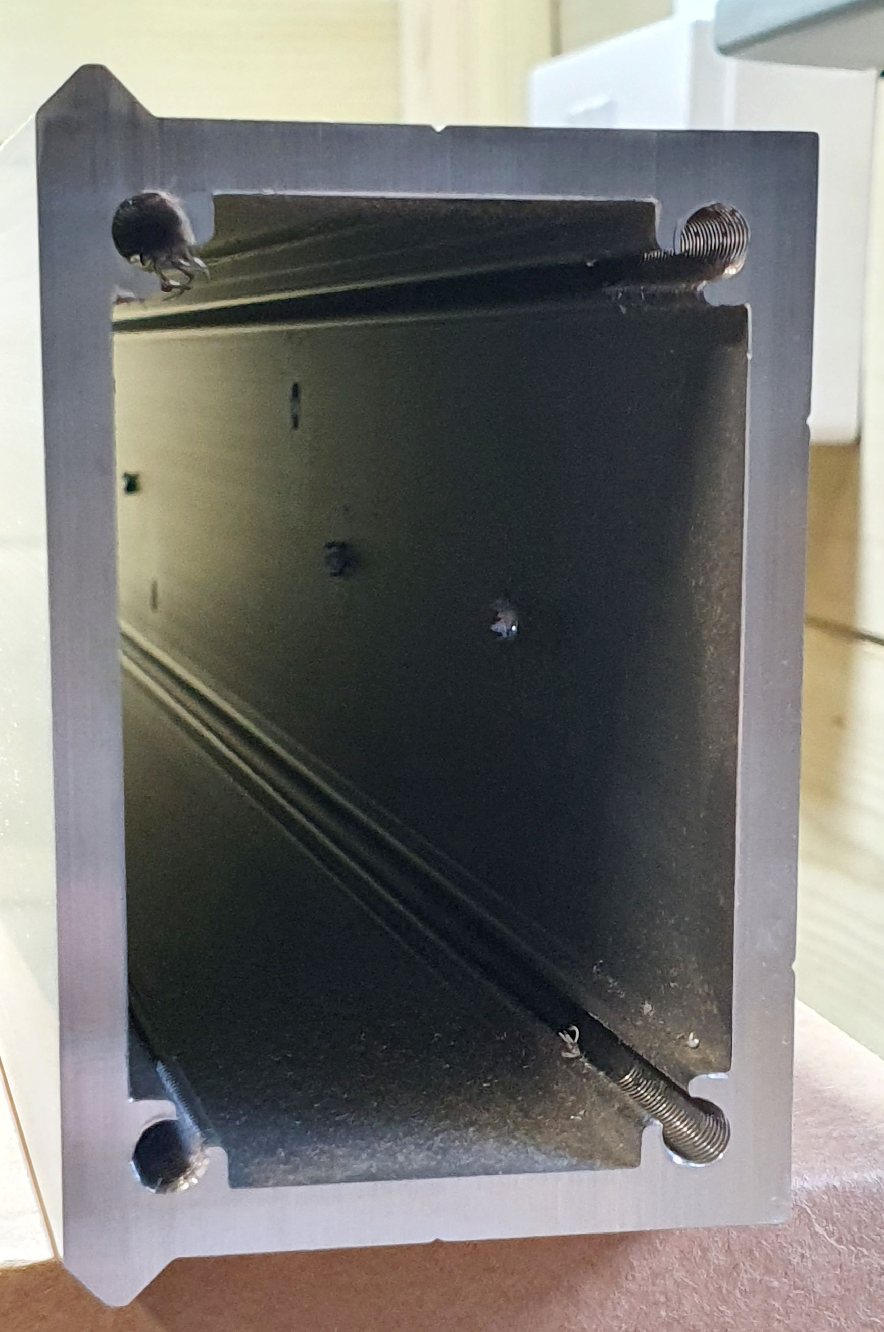
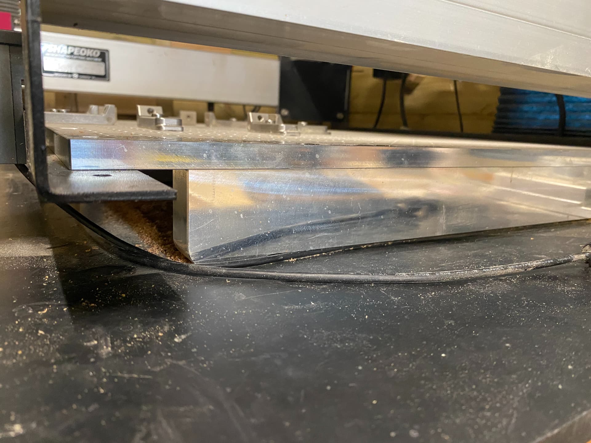
My machine extrusions are made using 5mm thick aluminium and the rectangular box section is 55mm wide by 80mm deep (2.16" x 3.15" x 0.2"). The baseboard is 12.7 mm (1/2") thick 6061 T6 aluminium. Underneath it is supported by three 23mm wide x 45mm high x 480mm long solid aluminium bars. (0.9" x 1.78" x 18.9").
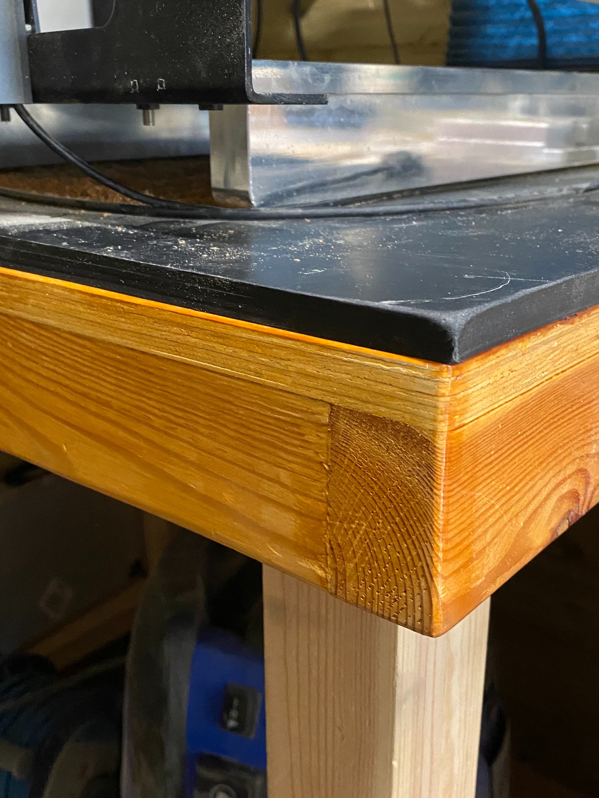
The whole plot sits on a bench made from 18mm (3/4") plywood sitting on the edges of CLS for a total of 75mm (3") depth to the bench top. It sits on double CLS legs braced with CLS legs of 75 x 50mm (3"x 2") in size. The top is surfaced with 12.7mm (1/2") industrial rubber sheeting for noise absorption and movement suppression. That square metre of material weighs in at 12kg (26 lbs.) and the whole bench is fixed to the wall and floor and has been tested to withstand 220kg (485 lbs.) of static weight.
I can tell you that my machine is as rigid as I have been able to make it. When cutting some very hard woods or 6mm (0.24") or 20mm (0.79") thick aluminium, the rigidity can occasionally give rise to chatter where the cutter is not ultra sharp and the workpiece is not held correctly.
pix.
Bench top and rubber mat on top of doubled CLS leg.
Extrusion cross section. To assist rigidity, I bought the smallest sized machine so each extrusion is 600mm (23.6") in length. Maximum workpiece envelope is 406mm square. (16")
@jomac Josh: Simply replacing the plywood with another sheet of MDF will not be sufficient in my view. Over time, the MDF base will sag. You need to build a structure of some sort to support the base. Some here have used aluminum extrusions, others have built torsion boxes. Most have simply constructed a table from 2 x 4 construction lumber, braced appropriately. (That’s how my table is constructed.)
You are correct that surfacing the spoil board will correct small variations in its flatness. However, it will not compensate for a sagging, unstable top. Further, you cannot rely on the flexibility of the feet to somehow compensate for a poorly constructed top. In fact, any flexibility in the feet is the enemy of precision.