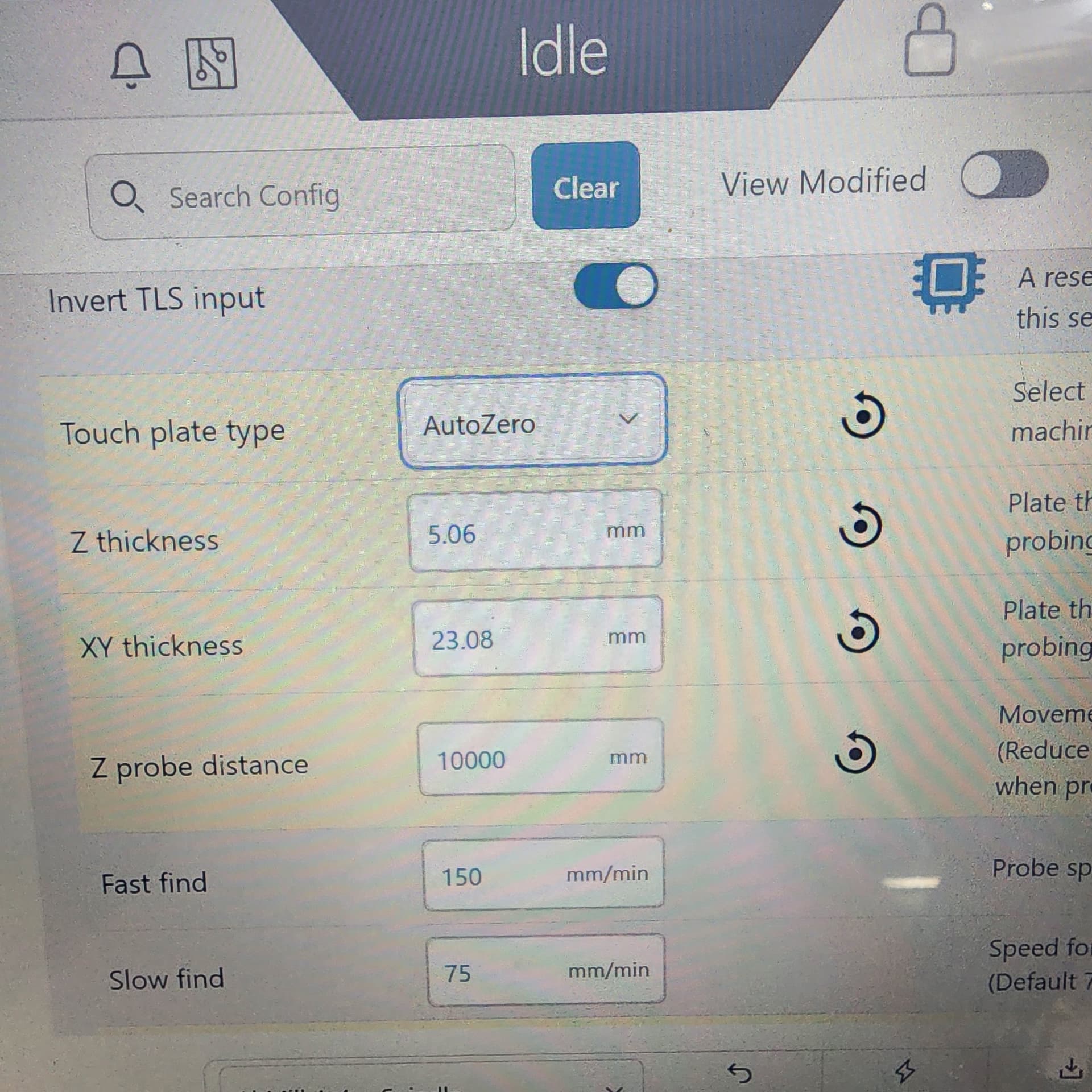
Hello everyone. My Auto Zero Touch Plate is approx. 2.92mm off on y axis and 2.85mm off on x axis. I have messed with the probe configuration in gSender 1.5.2 , but its still off. how do I fix this? So far, changing the xy thickness in gSender has no effect.
@EADURB I don’t have a solution, but I do have a question. Are you following these instructions
You’ll also have the option for choosing which tool you’re using, either “Auto” or “Tip”. Auto measures the diameter on straight end mills and bits. On the other hand, Tip uses the tip of v-bits, tapered bits, and ball nose bits touching against the bottom chamfer to determine its position. Using the correct setting will ensure the most accurate probing for your bit.
I have the same issue. I’ve been trying to do 2-sided carves and it’s not currently possible.
I just have a 5” square blank that I’m putting a 4” wheel in with a recess for a bearing, and it’s clearly not centered. It was off by 1/16” when I was using gSender 1.5.2 - I downgraded to 1.4.12 and it’s off by less, but still off - about 3/64”.
I’m using the option where I tell it the bit is 1/8 / 0.125” and doing XYZ.
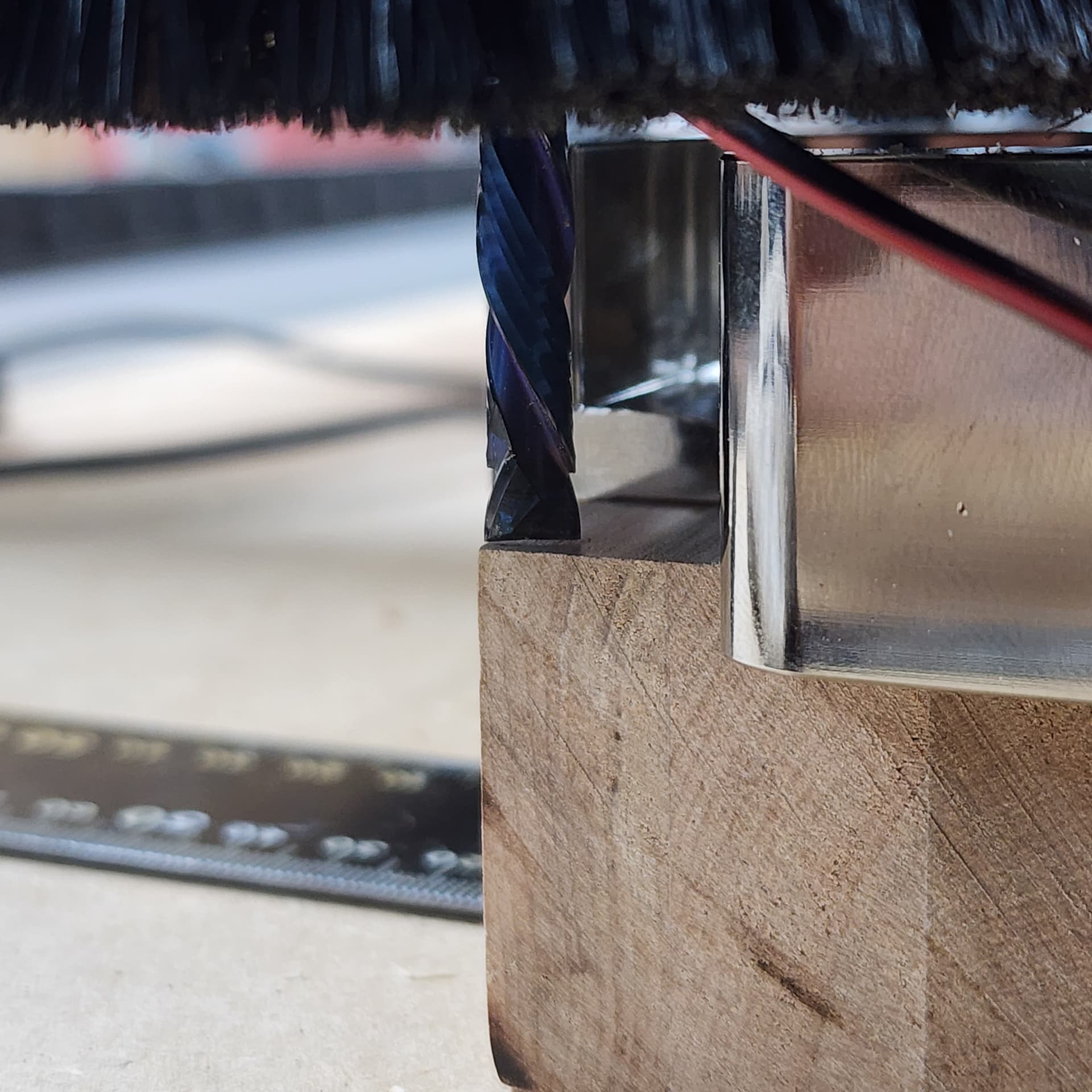
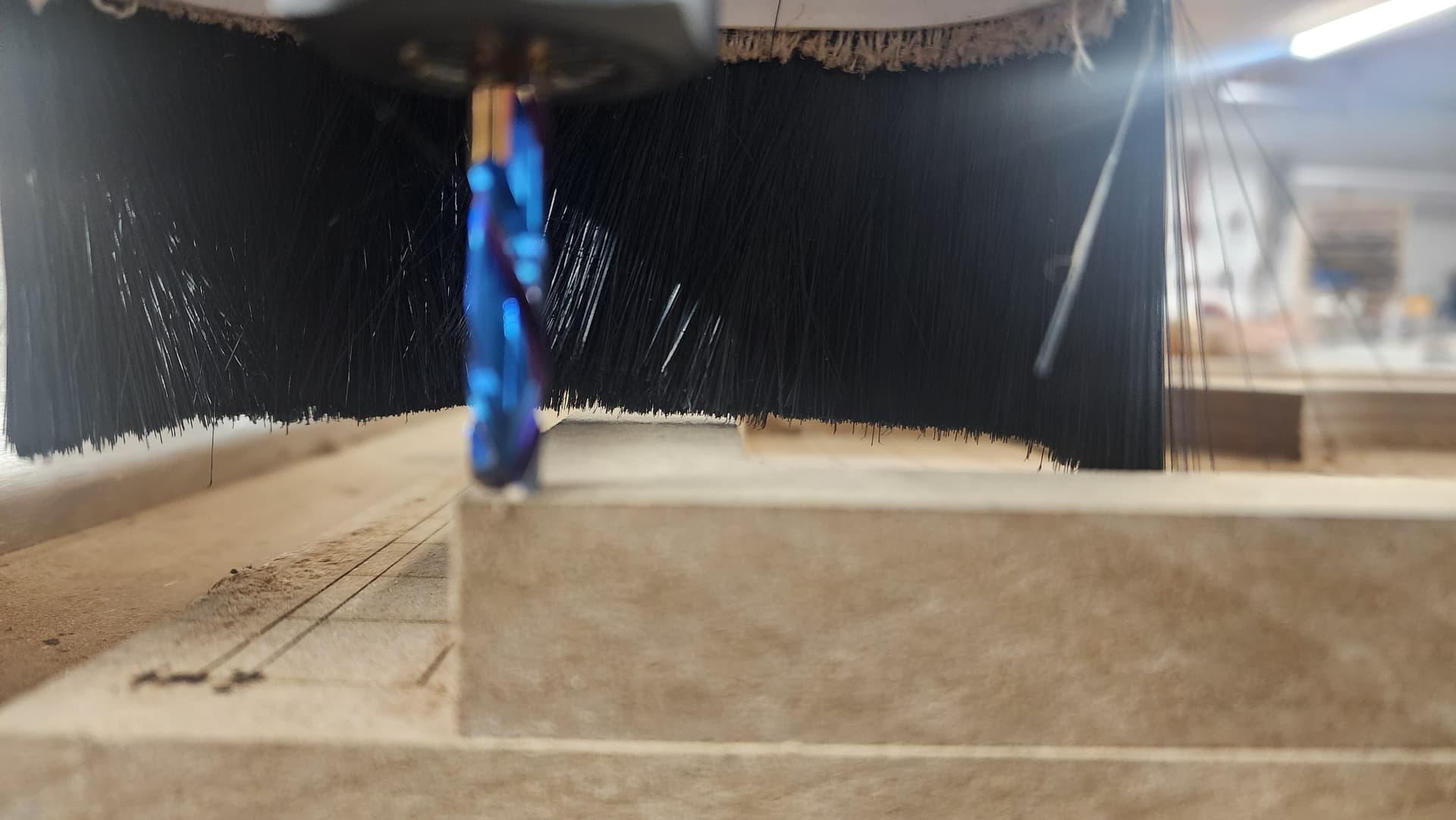
ETA I also noticed under gsender 1.5.2 it was zeroing as in the photos - with the bit over the work, as opposed to zeroing with the center of the bit on the corner.
It seems like it’s not doing this in 1.4.12 but it’s still off
@fisharmor I don’t have a solution for you, Joe, but while waiting for one, you can simply set your zeroes manually. Since you don’t reset XY0 when flipping the piece, if it is off a bit, it will not matter for the project at all. I generally set XY0 to the centre of my material. Since I do this by eye, I expect to be off a tiny bit. It has no effect on the two-sided aspect of any project, though.
Thanks for that. The trouble is I have the same issue as OP - both x and y are off by a bit.
If I flip on the X axis the Y will be off but the X will be fine.
If I flip on the Y axis the X will be off but the Y will be fine.
I can’t make a wheel if the bearing axis is off by 1/16 side-to-side, not even for this toybox….
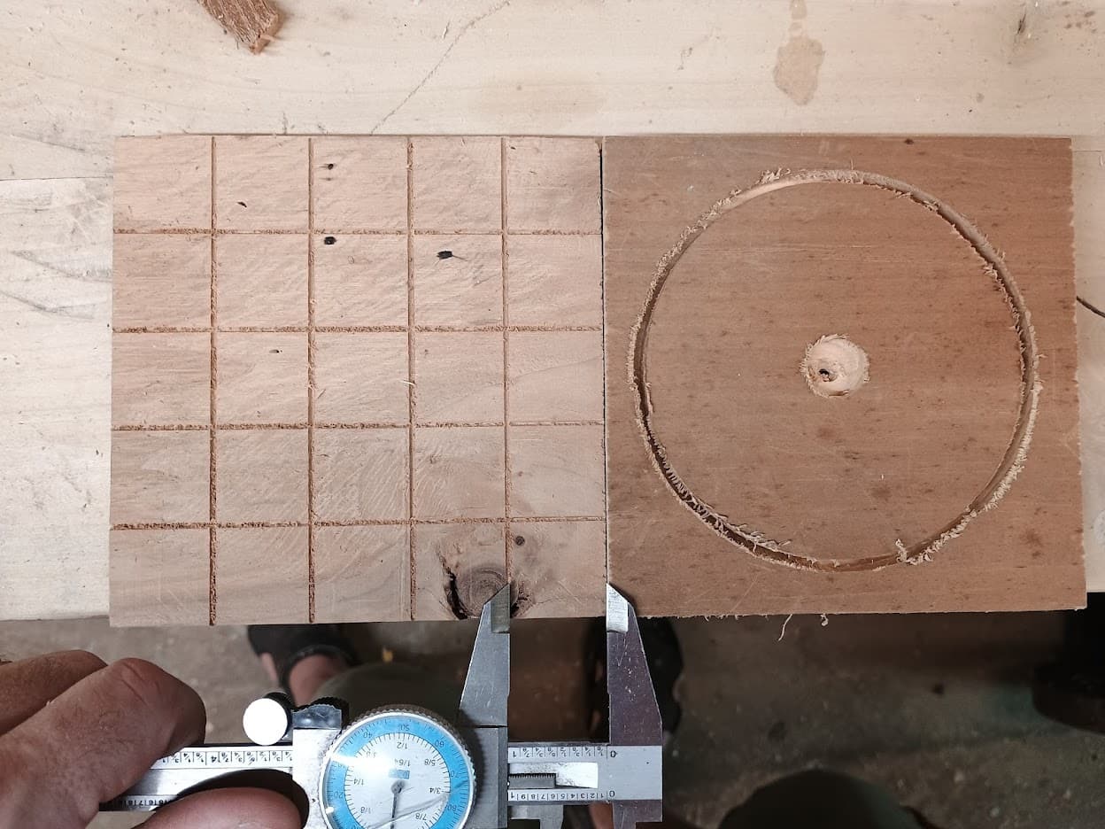
The photo shows the wheel I’m trying to make & you can tell at a glance it’s not even close to centered.
It also shows a test cut I did with just a 5x5 grid about 0.05” depth, and it’s dead-nuts on.
I shaved both blanks until they were both 5.00” ± 0.01”.
The differences between the two:
-
I modeled the wheel in Onshape and generated gcode using Kirimoto. The wheel is also cut out using a 1/8” bit (upcut, which is why it looks terrible) which was zeroed using the 1/8 bit option and XYZ.
-
I did everything for the grid prior to gsender in Easel, and the tool is a 60 degree V, zeroed using tip mode.
I’m gonna see if I can model the wheel in Easel to see if Kirimoto is doing something stupid and not centering it.
(I don’t have the money to make Vectric happen right now. It’s currently a “buy another computer” option.)
BTW this is how mine zeroed:
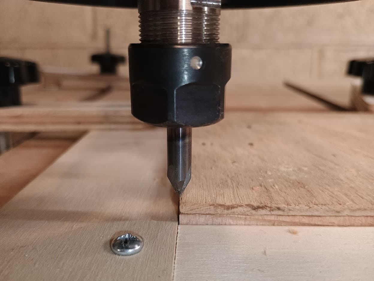
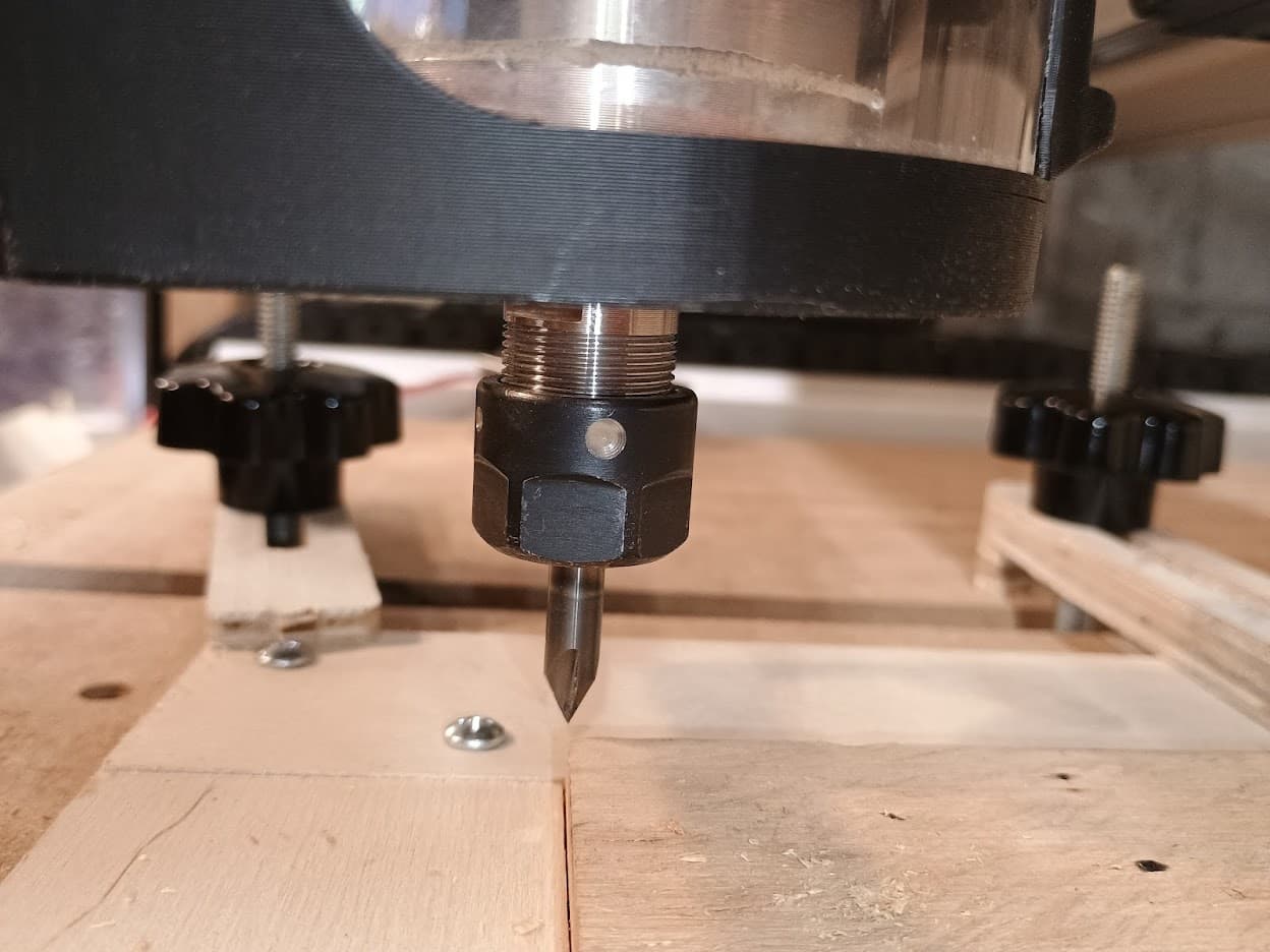
tl;dr I don’t think I have an issue with zeroing - I could swear the 1/8” bit was over the work last night but this is what just happened using gSender 1.5.3. Mine is probably a gcode issue.
If this was my support ticket I’d ask the previous reporters to test with a v bit & see what happens.
@fisharmor I wasn’t clear. How you are registering your piece before and after you flip it? I don’t use onshape or kirimoto, so I can’t relate to how they handle double-sided projects.
I use the “two-dowel” method to ensure that my two sides align. Using that method, it does not matter is the XY0 is off. It will be off the same, only mirrored, on the flip side.
Well I was assuming the model is going to be in the center of the piece - and as far as I can tell, it’s supposed to be in Kirimoto.
I have a square L-shaped brace clamped to my spoilboard which I made sure is aligned with my X&Y axes, and, provided the workpiece is centered, I should be able to zero to the piece when it’s clamped next to the brace, then flip either way - and therefore skip using dowels.
Everything checks out except for the cutout not being centered as advertised. I only initially thought it might be an issue with the autozero plate.
@gwilki, could you expand a bit on the dowel method? I assume that you have your stock, drill two holes through the stock and then into your spoilboard. What I can’t quite picture is how you set the origin on your model and work piece. Do you set the x/y zero to exactly the middle of your stock? If so, how do you make sure that you are actually exactly in the middle?
The only thing I can see is drilling the two dowel holes with the CNC a known distance from each other and then setting your x or y zero exactly half way between the two drilled holes.
I found a nice example of the dowel method on YouTube so no explanation is needed after all.
@Jens I apologize for the late reply. Motorcycling was more of a priority than CNC yesterday.
I don’t know what you found, but mark lindsay cnc on youtube is likely the best out there. He has couple of step by step tutorials on double sided jobs. They are done using VCarvePro, but I would think that the concepts would hold true for other applications. Vectric has a few, too.
A lot depends on what your project is. Clearly, if all we were doing was to cut out a rectangle and we needed to do it two-sided because of the thickness of the material, then it would be simple to ensure alignment. However, when the job is a chess piece, for example, where the top and bottom are not simply a mirror image of each other, but they must align, then things get a bit more complicated. That’s where proper alignment of the two sides, and a capable CAD application come into play.
I’ve done close to 100 of them, so if I can help, I will. That said, I’m not as expert as Mark.
@fisharmor I’ve not used KiriMoto. I looked at it early on and thought that it would not be best for my applications. If it does default to putting your vectors in the centre of the material, and if it does mirror the back side, you are on you way to success. I would still use the dowel/locating pins method to ensure alignment, but if another method works for you, that’s all that matters.
Edit: I just looked at Kirimoto for the first time in years. All of the machines that it lists are 3D printers, so from the little that I know of them, double-sided projects are not an issue. The other thing that I found is that there is no guarantee that your model will end up in the centre of the workspace. So, that may be a factor to look at when trying to addres your problem.
FWIW, for your wheels, you would be much better served by using a CAD/CAM application geared to CNC routers. Creating a 3D model for those is a very inefficient way to go about making them. A CNC application would do them as a single-sided job using profile toolpaths.
I believe I found the issue.
I used zero method ‘tip’ and it was fine.
I used zero method ‘auto’ and was able to do 2-sided cuts just fine (a little misregistration, but that’s my clamping method).
In my case I was defining the bit as 0.125” and it was off on the X axis by 3/64-1/16”. I verified last night that when I zero it using defined bit size of 1/8” it’s zeroing with the entire bit parked on the material as in Kerryh2012’s OP.
Kerry is also using a 6.35mm bit and says he’s off by 2.92mm - which is pretty close to half the bit diameter.
The issue seems to be defining the bit diameter in the zero process. It parks the entire bit diameter on the work as in the initial photos, and therefore the entire carve is going to be off by 1/2 the bit diameter. I literally watched it do this last night between defined bit diameter and auto methods.
I’m not sure if there’s a way to examine the instructions gsender is sending to SLB between the methods… or if there’s a place to make official bug reports? But for now just do the 4-touch auto method, spend 30 extra seconds and it’s probably fine.
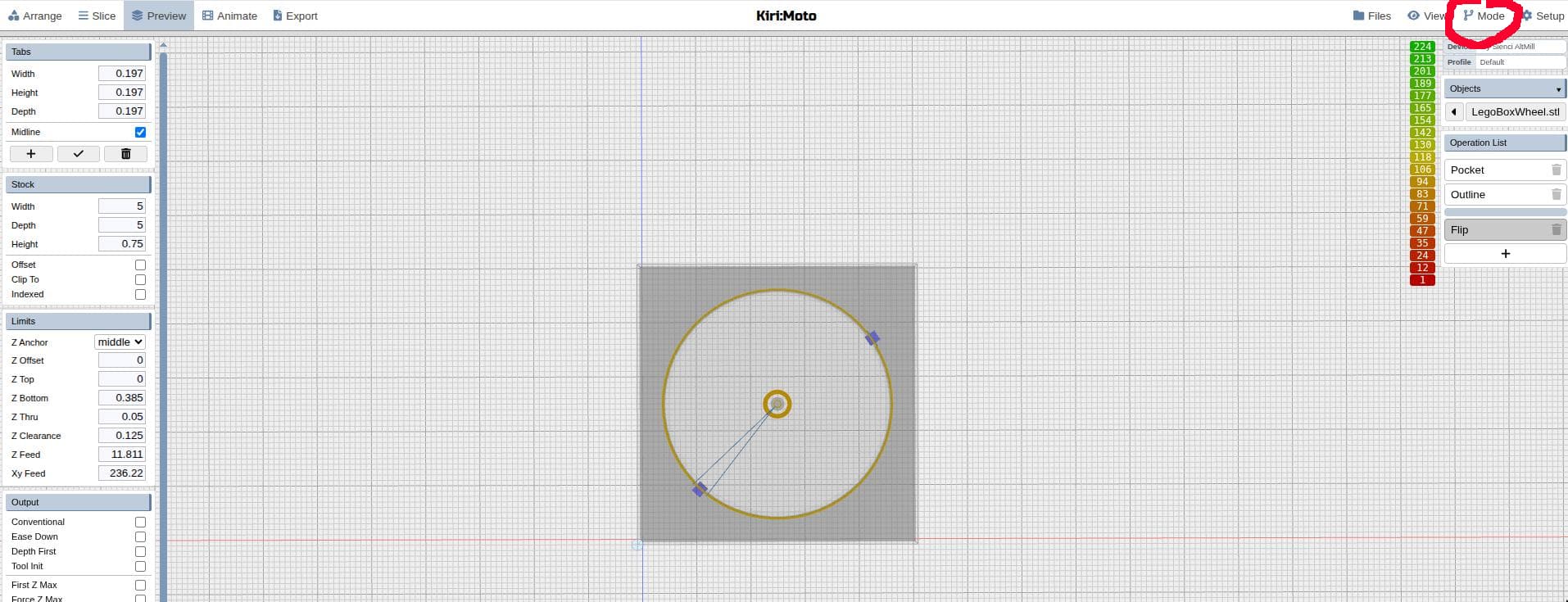
By the way, yes Kirimoto is a 3d printing app - that has a CNC add-on. It’s a separate mode you have to go into:
I did a 2-sided job because there are bearing races on either side of the wheel. So there’s a 5/8” pocket on either side only 1/4” deep, with 1/4” material left in the middle, and a 1/4” through-hole.
Could it have been done with a single bearing race on one side? Absolutely, but I’m brand new to this and wanted an easy test case for a 2-sided cut.
TBH the biggest gripe I have with Kirimoto so far is I haven’t figured out how to determine cut order. So it skips around in the job in ways that don’t make sense and waste time with unnecessary movement. That doesn’t have to get fixed until this is trying to become a side hustle.
I know Vcarve would have made shorter, easier work of this, and has better toolpath options - and (Vectric, if you’re reading this pay attention) if it wasn’t Windows-only I would already have purchased it.
Welcome to ‘windoze haters anonymous’
@fisharmor Understood. Tks. I just opened Kirimoto, but did not see an option for double-sided projects. It’s not important that I do since I have VCarvePro. If Kirimoto does not have that built-in capability, I am guessing that you are doing two single-sided jobs to complete your project. Correct?
Just an FYI, I run windows so I can only go by what many others say about running VCarve on a Mac. You would know more about this than me, but it is possible.
Yes if you look at that same screenshot, the RH text says “Operation List” in a blue box, and you can see I’m doing a pocket, outline, then Flip - it’s clunky IMO because you click flip and then there’s a sub-option to flip it over, and you choose completely separate tool operations for that side. It keeps the tabs where they need to be, and you still generate 2 gcode files.
I think you can see on the left where I set ZBottom to 0.375, meaning each cut is only going to the Zcenter of the piece.
There are pin options, too, including a 3 pin option that’s supposed to make it impossible to flip it wrong, but I haven’t gotten there.
Yeah it’s an opensource project for sure but it strikes a rare balance, because unlike FreeCAD it actually works, and unlike Blender it’s not quite a Pacific Ocean of grey-on-charcoal checkbox soup.
@fisharmor Clearly, I missed all of that. My apologies. The 3-pin option should make it impossible to misalign the two sides. I use that method in VCarve and have never had an issue. I hope that you get this to work out.
The true test will be when summer is over and I can get back to the scallop boxes. I don’t see how this will not be a problem as i have 4 work offsets doing 2 top and 2 bottoms on this job.
fwiw, I just did some testing since it’s cool enough in the shop now. Tip and auto work correctly. This behavior only occurs when setting the bit diameter. I am confident that this wasn’t an issue in previous versions. I have done a lot of 2 sided carves that would have been scrapped if that were the case. Saving 2 moves to zero the bit is preferable with a known bit diameter.