Native support for touch-trigger / 3D probes

So, something I have seen proposed in another Facebook group, (GSENDER related, but definitely would require some kind of probe.)

I am not sure if I can explain it properly, so I will attempt to use the example that was proposed.

The Short version, It would be nice if the Longmill could be used to ā€œfind the workā€

One of the groups I belong too, is for Cutting boards, people will make them up, glue up, sand and then seal.

A few individuals, have started to put Bevels, ā€œDrip Traysā€ , Logo or Inlay’s into the work. but struggle with lining them up. and after 30-40 hours of making a cutting board, the last thing you want is to make a mistake on the CnC

I would like to be able to have the longmill, do a kind of Find, and have it define the actual workpiece, then based on the results, it sets the XYZ 0 at the center of the work. (as well as report out the Work dimensions.)

Then I know the Center of the Work is true center. I could put a Bevel on the block of wood, because I know EXACTLY the mm to the detail

Truth be told, with this kind of information, you could tell if your project is skewed as well ,
Because a X1Y1 - X1Y550 and X500Y500 - X500Y450 reports the block is not centered properly.

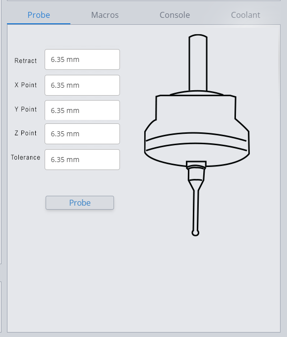
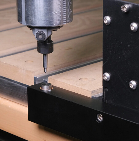
Probes available from Ebay

1 Like

@Menglor As I’m sure that you know, Stephen, it’s simple to do this now without the expense of a probe. I have set up my Mill and I believe that @Heyward43 has, too, to be able to make repetitive carves accurately and simply. Like you, I carve cutting boards. I also carve picture frames that I have assembled off the Mill. I use the Mill to carve intricate details into the frame. If I’m out at all, I’ve wasted a lot of time. I’ll be interested to see if gSender will do this in the future. Until then,you may want to pass along to your friends on other Facebook pages that it can be done now.

I see what you’re describing here Stephen, though I’ve never heard it being applied to finding work exactly in the way you describe. Interesting.

I can say that as of now there is a easy-ish way of accomplishing the same final result as this without a probing sensor which is to cut out a pocket in a piece of sacrificial material - it doesn’t have to be very deep at all - which matches the outer dimensions or contour of your item. Then, with the origin point of that cutout already known you’d be able to place the item within the pocket, hold it in place, and perform the engraving, drip tray, etc. exactly lined up. This would also automatically take care of ensuring the item top is parallel and squared up to the mechanics of the CNC.

I’m sure you’ve already heard of this method but I figured I’d mention it for completeness :+1:

1 Like

@chrismakesstuff This is a similar process to mine - but somewhat different. :grinning:

I have drilled a series of 1/4" diameter holes in my spoilboard along both the X and Y axes of the Mill, using the Mill to drill them. I believe that @Heyward43 has done something similar. When I want to engrave a picture frame, for example, I place 1/4" dowel pins into these holes. I snug the frame up to the pins and clamp/tape/glue the frame down. Now, I know that the frame is perfectly aligned and square to the Mill’s X and Y movement.
I set the X0Y0 to the front left corner of the frame, using the touch plate and probe function in gSender. Obviously, I cannot set them to centre as there is no centre. However, even if there were, as in the case of a cutting board, I would still set to the front left corner for the sake of precision.
This method has worked perfectly for me for several cutting boards and more than a dozen picture frames. It’s not my ā€œinventionā€ as many others both here and on other sites have adopted the same process. It seems to have withstood the test of time.
In terms of non-square/rectangular items, I have used your method, Chris. I did two oval picture frames. I cut a pocket into a waste piece of MDF that precisely matched the outside dimension of the frame. Without moving the MDF, I placed the frame into the pocket, then carved the graphic onto the frame. It worked perfectly.

2 Likes

Hi, I’m trying to use the PGFUN 3D touch-trigger probe with my shapeoko running gSender alongside my fixed toolsetter. I’m struggling to get them to play nice together with the auto toolchanger wizard, it would be really great if there were a panel similar to the current probe panel to execute probing steps, and if the Z offsetting could be natively handled with the auto tool change wizard.

If anyone has some suggested workarounds or macro workflows, that would also be greatly appreciated.

1 Like

I don’t know if you have written any macros before or not. I recently made my first.

The basic structure is declare the variables needed for the macro. save the initial state, do what you want to do, and then restore the initial state.

I found this section User Guide Ā· cncjs/cncjs Wiki Ā· GitHub to be very informative. gSender being a descendent of cncjs all info there is relevant.

If you need a gcode reference try LinuxCNC "G-code" Quick Reference you can get a feel what different gcodes do at the start and and click to get the full rundown on the ones you’re interested in.

1 Like

Thanks for linking me to the cncjs guide, that’s helpful. I’ve written a few macros, at the end of the day it’d be great if this could be offered out-of-the-box, but I’ll give it a go and share any workflows that are successful

1 Like

Hi, I was wondering if there’s any plan on the roadmap to support 3D touch probing for faster and more flexible workpiece indication.

1 Like

Thanks M.P.

Bookmarked for later reference. I know I’m going to need it someday, for my nead is bubbeling and one day I will step out of my lazy corner and macro one out.

I feel there’s a lot to be discovered, a ton to be learned. The only thing I need is a bubble to keep popping up. I see people doing awesome stuff with auto dust shoes, auto tool change and whatnot.

I have set myself a goal to one day be that guy that posts something like that, and drop a few jaws.

1 Like

3d probing works , you can select all 3 axis and use the small chineze probe, i used a relay in between the probe and the board, i had one board burned out, probably due to miss wiring, or the probe releases a small current on the switch side, idk, but i didn’t what to burn the second one so i added a relay

I’ve recently gotten setup to compile GSender and was able to package it as an executable today, so I am starting to think on a potential capability I would like to add. I have a 3D touch probe and one of the things I’d like to do would be to key in a known X, Y, Z point where I expect a part or fixture to be along with a tolerance (how far off that point am is acceptable) and using a retract height (z) move to the location and probe to confirm.

Now, I realize this can get tricky and one could easily crash if you are not careful. The thought is there needs to be an approach distance in which the machine needs to slow down, and then do the fast touch/slow touch from that position. This would allow fast movement to what should be a safe point to probe from, followed by the actual probe.

The main difference here would be this would not reset the X, Y, Z since that’s not the purpose of the probe. Instead if it ends up probing outside of the tolerance specified, or doesn’t probe at all, it could alarm. Although I’d like to add a find center of radius feature as well.

Anyway, just looking for thoughts on how you might like to see a 3D touch probe implemented in GSender. Some of you are probably using macros to do this sort of thing, but personally I would enjoy the ability to use the probe for such sanity checks, under the probe panel in the software.

1 Like

I think it’s cool that you are working on this and that you are able to build gSender.

I’m a hobby programmer but most of programming has been done in C, C++ and Rust. I’ve also used various other languages when needed like Python, Lua, Bash, PHP, etc. I have only minimal web experience like a static website on my little home server.

Long story short is I know myself and at least one other member would appreciate it if you could provide some instruction on building gSender. I think I could learn some JavaScript easy enough I’ve just never really wanted to before gSender came along.

I’m totally lost as how to build gSender. We have a thread on building gSender. If you have the time it would be cool if you could help us there.

I don’t know how hard it is to build or explain so I don’t know how much work I’m asking you to do. If it’s too much don’t worry about it.

Michael

1 Like

Absolutely. I got some help as well that pointed me in the right direction, but it was over on GitHub. I’ll go post on the thread you linked.

1 Like

I started using GSender with my Nomad because of my desire to use a 3D touch probe. (The small and inexpensive one in your sketch :slight_smile:)

XY probing is relatively straightforward but I would really like to be able to use it for Z as well, in a way that integrates with the fixed position tool height sensor. I’m thinking there are two basic possibilities here: (1) gSender could know the fixed Z offset between the tool sensor trigger point and some other fixed location on the machine (like the machine table surface). Then you could 3D probe Z on both the work and the machine table and calculate the ā€œinitial tool lengthā€ of the probe.

Or, (2), I could make some sort of physical contraption to repeatably register the 3D probe to the machine spindle nose. Then gSender would have to know both the absolute Z coordinate of the tool sensor trigger point and also the ā€œtool offsetā€ of the 3D probe. That seems like an ideal solution for ease of use, but it also seems like halfway to a full tool offset table implementation like you would want for a machine with an ATC or some other way to repeatably mount tooling. Which would certainly be a nice feature, but perhaps quite a bit of scope creep vs. other ways of integrating the 3D probe.

This part reminded me of a macro I made.

Now my macro was just for setting Z zero to the spoil board but what I did is use a user defined value for the maximum stick out of their longest bit. I think if you know the stick out of the probe and where the fixture is supposed to be then you can do like I did and rapid move most of the way and then probe, slow probe. With a probe the users stick out wouldn’t change much assuming it’s always mounted the same. Obviously you or the user need to add some safety margin. With my macro for bits the short bits take a little longer than my long bits but it’s much faster than before I added the rapid move in all cases.

I’ve always been interested in a touch probe mainly for doing carves on an existing item. I’d need gSender to have the ability to do a grid of probes and make a height map or mesh that you could then bring into some CAD/CAM program.

What your currently working on seems like it might be a step in that direction.

@ajwitte Hello Andrew, welcome to the group.

First off I’m assuming that in your first method the probe is in the router/spindle and the second it’s mounted at an offset.

I thought I could simplify your first method but then I realized it’s only because I have Sienci’s sensors for homing my LongMill. If you can home then you have your two points, home and the tool height sensor. I think that’s enough but requires switches or sensors.

I’m not sure I understand your second method at all. Is the touch probe always mounted? I don’t see how it could be without being in the way during carving. Maybe it can be and I just can’t visualize it. Why does it need to ā€˜listen’ to the spindle noise? What information that does that provide that G-code or gSender, with start, stop, pause, and resume actions can’t?

Thanks for the welcome!

For my second method I would still be exchanging the bit and the 3D probe, but I’m envisioning putting some sort of collar or something on the 3D probe that allows it to be inserted the exact same height every time.

And yes, I neglected to mention that my machine does have homing sensors. (Honestly, forgot that many grbl machines don’t… oops!) Obviously that helps although I don’t think it’s strictly required for my first method, if someone did have a workflow for a fixed tool length sensor that doesn’t require homing.

Okay, so in your second method the offset was what I called stick out, I think. I’m not sure about the correct terminology but when I read offset I thought of the laser mount XY offset.

I guess I was tired last night because I read that as spindle noise multiple times and got very confused. :laughing: That’s what my ā€œlisten to the spindleā€ question was about, silly Michael. The question is not without value though. It’s worth a laugh!

It is my understanding that, if your machine uses a collet, by the very nature of the collet action you can not guarantee positioning.

Just to clarify my understanding, you’re discussing a way to perform a tool change after probing the Z origin, and you want to be able to offset the Z based on the length of the tool you’ve inserted?

For Shapeoko the bitsetter is designed exactly for that purpose. That’s more for tool changes during a job and is really a convenience and I rarely use it. It looks like this:

Personally I would set my X,Y using the touch probe, then set the Z after changing to the tool manually. I find that to be as fast and reliable for me as trying to use the bitsetter, and to use the bitsetter with gsender you’d have to use a macro (someone posted a macro on here for it).