I’m a UGS user trying to move over to Gsender. The only problem I’m running into is the XYZ probe setup. There isn’t an input field in the standard block setup menu to set the distance the spindle/bit moves after the Z probe to clear the edge of the touch plate. When running the probe it appears the bit moves about 1" in the -X direction to clear the touch plate edge and that this is hard coded into the routine. I have two touch plates and like many you see on the market, mine have holes at the xy zero point to facilitate a different type of probing. This means I can’t position my bit close enough to the edge of the touch plate to be able to work with the default xy offsets that gsender is using. In my case, I need a distance of about 1.5 inches to be able to use my touch plates.
My suggestion is to add input fields in the setup menu for these X and Y “offsets”. That would permit the use of any configuration of touch plate to be used with the program.
I have a similar issue. My touch plate has a hole in it also. I can’t figure out how to systemically change the probe to not use that hole for the z probe.
I’m not sure I understand your issue. If you’re just doing a Z probe you can position the bit anywhere on the touch plate. My understanding is that the hole is for use with an electronic probe, the kind you see on a CMM inspection machine. Unfortunately, if you’re trying to do an XYZ probe using the standard block routine, the hole is right in the area where you need to position the bit for the initial Z probe part of the routine. This is why I am asking for variables to be added in the config menu so that bit can be positioned in different locations at the start of the probe.
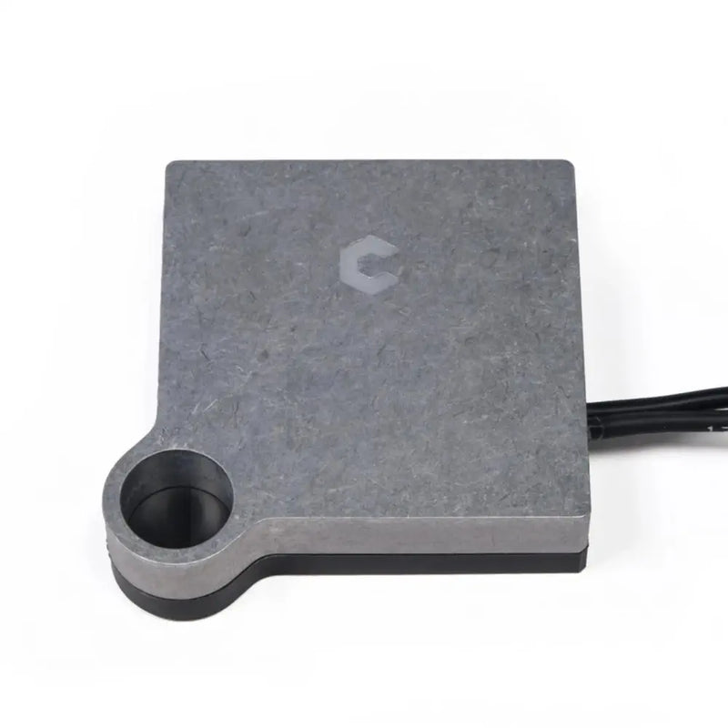
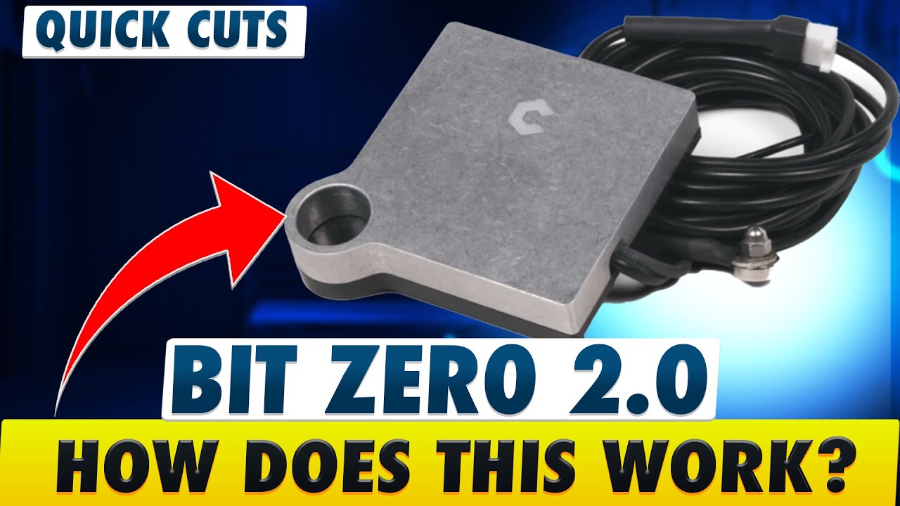
If so there is a setting in gSender to select a BitZero probe, Config->Probe->Touch Plate Type.
The way the BitZero touch plate is designed the center of the hole is at XY 0. I don’t have one to test but I’m guessing that setting will use a different probe routine that finds the center of the hole for XY and then, or maybe first, Z as normal. Not knowing if Z is done first or last I’m not sure where the bit should be at the start of the probe. The picture of the probe in the probe tab changes based on probe type but the BitZero type uses the AutoZero for the picture so that doesn’t seem to help.
Maybe that’s enough to get you pointed in the right direction and get it figured out.
EDIT: If I had to guess I think you would start with the bit partway down the hole or just above it for an XYZ probe. That’s seems like the logical way to program the routine. Any other way would risk missing the hole. I’d keep the stop button handy til you got it figured out just in case.
EDIT2: It occurred to me that I could test with the wrong block at least a little. I set my mill to use the BitZero with an XYZ probe. After the continuity test I hit the start probe button and the probe moved slowly in the -X direction without going down first so starting with the bit partway down the hole should be the way to go.
I’ve got a couple of projects going on, so I can’t test this for a couple of days. But I did search through The Gsender documentation and there is nothing in the documentation that states what this routine is for, how it works or how to use it. Perhaps someone from the Gsender team can chime in and tell us what this option is intended for.
I finally got a chance to test this on my touch plate and while it does work as shown in the video, I am not getting correct results. The X zero looks right on, but the Y zero is off by about 1/8” and the Z zero is off by 2-3 mm. I’m using a 1/4” steel dowel to do the probe and I can’t see any issues with the setup, so I don’t understand why this isn’t working.
I suppose I should start a new thread in the Questions section about the problem with the Bitzero process. If I can get that to work, it would serve as a work around, but I would really prefer to use the Standard Block process for a couple of reasons. First when probing X and Y, the probe touches in the hole in both the + and - directions so when it is touching in the direction away from the workpiece, it can and does move the probe plate away from the workpiece. You have to physically hold the touch plate in place or you will get a bad reading. Secondly, when Z is probed, the bit moves down at a faster rate for the initial touch and then a slower rate for the final touch, just like you see on other probe procedures. But it does not do this on the X and Y probes. It only uses the faster rate and this may compromise the accuracy of the X and Y zero positions. Given those points, I hope the Gsender developers will consider adding the setting inputs I requested in my original post in this thread.