A long one.
This is frustrating me, and I’m trying to nail down how to fix it
The project, Fibonacci scales, a bit of precision is needed.
Machine, Gemitsu 6050 Plus a little over a year old and up to no not used much.
I can’t find any slop in the machine and I used Machine Tuning to check its accuracy and as far as I can tell it’s right on.
gSender 1.5.7
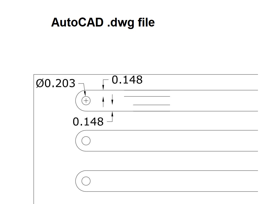
Design SW, AutoCad 2000
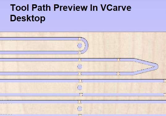
Gcode generator, VCarve Desktop 10.515. I import the Acad .dwg file.
Stock, 1/8” pine.
Cutter, 1/8” X ½”, 2 flute carbide with ¼” shaft.
RPM, 27,000
Feed rate, 40 in/min
Cuts. The beams and holes both using profile as the holes are an odd size for barrel nuts.
3 Passes.
.020 last pass for cleanup.
Total cut depth .140 to cut through the stock.
I have to use .150-.170 to get to ~.125 inch depth of cut.
The workpiece does not move.
The router in its mount and the bit in the ER-11 collet do not move.
Problem,
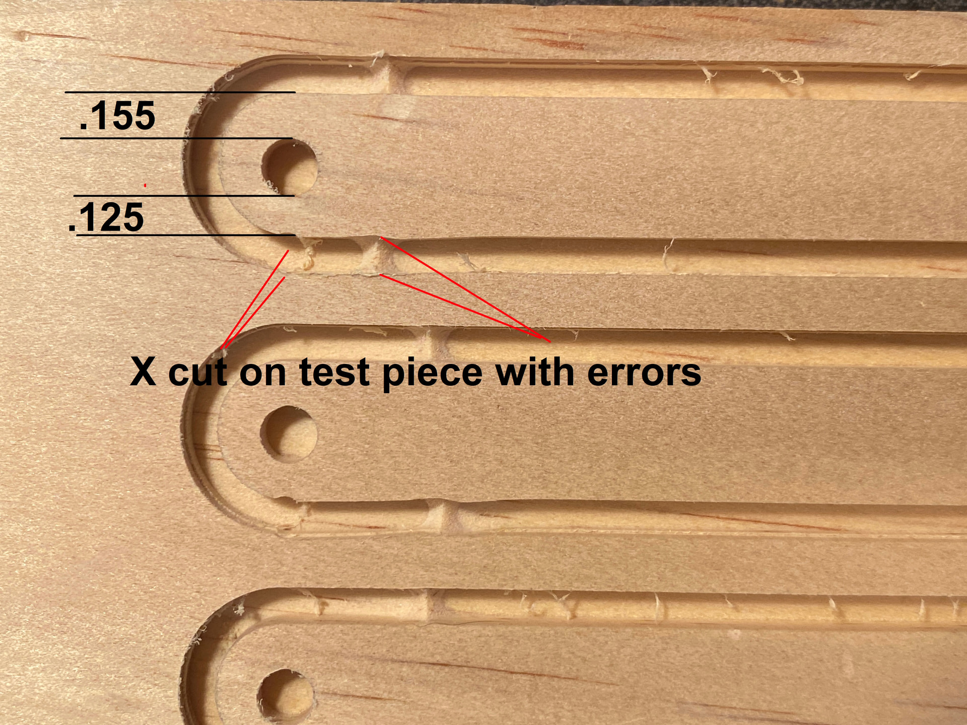
As you can see from the pics the lack of precision is a bit alarming.
The test pieces are ½” thick to test of stock movement and bit wander with the .125 depth of cut. The stock doesn’t move, but the bit is “wandering”
The Acad pic shows symmetry as does the VCarve preview.
The actual work pieces not so much.
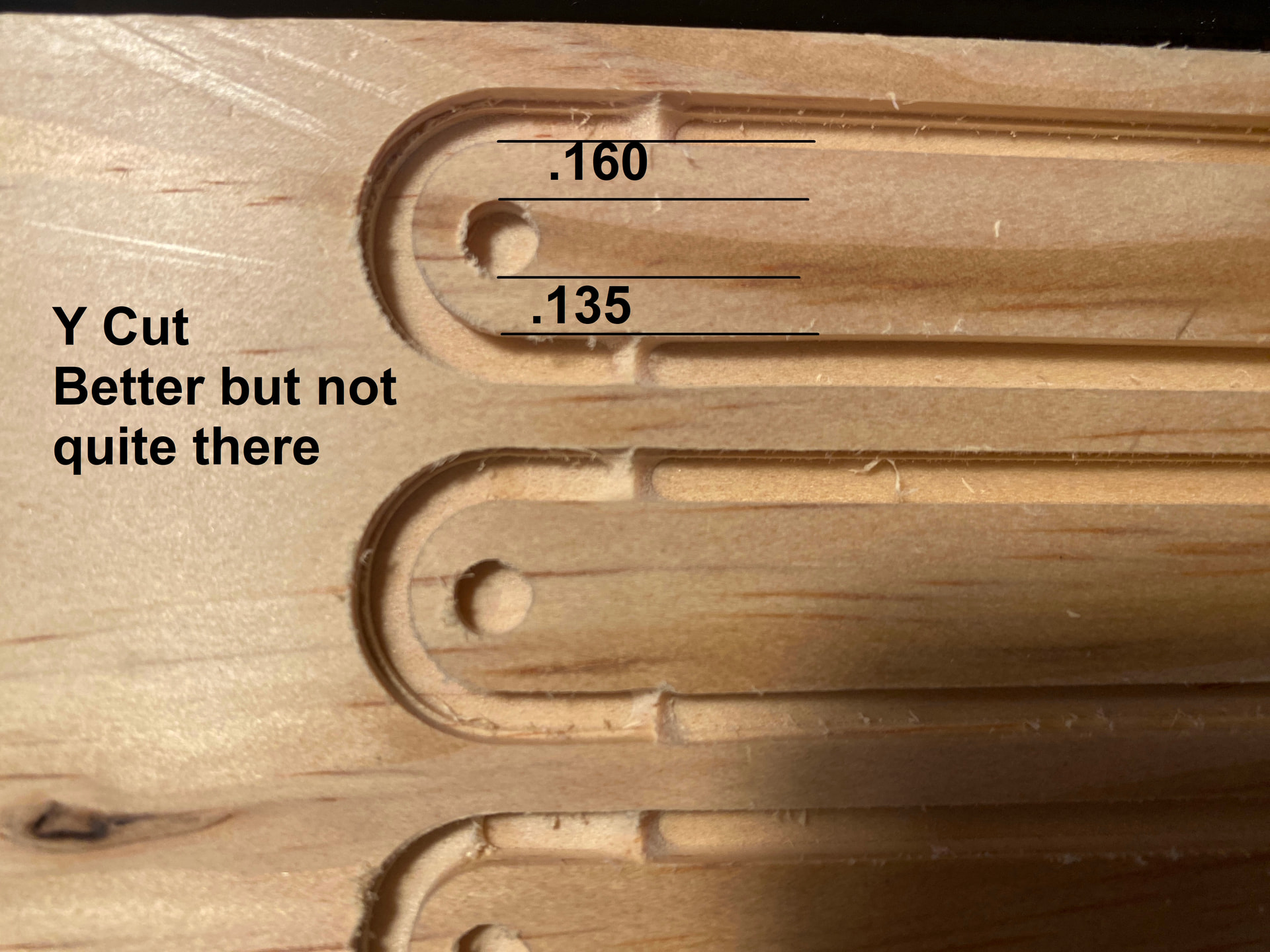
I’ve cut this on both eh X and Y axis of the machine with both the 1/8” and ½” stock.
The pics of the work piece tell a story.
The cuts are not accurate, and the holes are off the center line by way too much.
It was suggested on Facebook to try another Gcode sender like UGS.
I’m really comfortable with gSender and don’t want to start over.
I’ve even tempted to roll back to v1.4.11.
@Kevin745 I really doubt that the problem is with gSender.
I’d guess an issue with your CNC or a combination of hold down method and feeds/speeds causing movement in your workpiece. But you say the workpiece doesn’t move, so I don’t know.
What does this mean exactly: “I have to use .150-.170 to get to ~.125 inch depth of cut. The workpiece does not move.”
That’s what I thought you meant. That would make me want to check the accuracy of my CNC. A dial gauge mounted to your router/spindle would be useful to compare the gauge with a jog defined in gSender.
Usual preface, I’m with PreciseBits. So while I try to only post general information take everything I say with the understanding that I have a bias.
My guess is that you are dealing with deflection (bending) of either the tool or the machine. If this is a slotting cut and it’s changing direction around the round ends in your picture it’s even more likely. The simple version of this is that the cutting forces are bending the tool or machine into the conventional side of the cut. Meaning it will double the error if the lines you are measuring against are in opposite cut directions.
There’s a way you can test it. I went through it here before:
This could also explain why you are having to plunge “deeper” to actually cut through. As if you are bending by enough the tip will move out away from the bottom. Although there are a lot of other things that can do this like a collet that isn’t gripping enough or loose mounting of the spindle/spindle mount (although you said you already checked this).
Easiest way to fix it if this is the issue is to lower the force. So reduce either pass depth, stepover, or chipload (feed). Be careful with the last one. If your chipload (feed) is too low you can actually increase the cutting forces as eventually you will be grinding and not cutting.
Hope that’s useful. Let me know if there’s something I can help with.
Much better.
I continue to climb that learning curve.
What I did was reduce the feed rate 25”/min, reduce the RPM to 18000, and set the plunge rate is 10”/min.
In VCarve says I have a chip load of .001. Seems low, but it’s working.
I don’t have an cut edge mistakes and the holes are just about right on center line.
With wood, I’m OK with what I’m getting now.
Vectric has always had issues with chipload calculations. That is not actually a 0.001" chipload. Chipload = Feed / RPM / Flutes or in this case 0.00069" (25/18000/2). That’s under what would be ideal. You will probably get better results by dropping the pass depth and increasing the feed. Doing this proportionally will keep the same relative cutting forces. e.g. cutting half as deep at twice the feed is roughly the same cutting forces. There is some difference in the direction of the force due to the helix (flute twist). But something close to there will probably give you better results.
There’s no reason to drop the RPM. The only reason to drop the RPM is if you are over the surface speed for the material or you don’t have enough feed at that RPM to hit your chipload. So as an example if you wanted to keep the same chipload and cutting forces you could run at the original RPM of 27,000 with a feed of ~37IPM. This makes me question if there’s actually something else going on as that is very close to your original that wasn’t working. Did you change anything else?
Noting else has changed.
When you say dropping the pass depth, I assume you’re suggesting adding passes?
Adding passes and increasing the feed kinda makes sense.
I’m still learning.
I’ll give that a try on a test piece and let you know how it goes.